10.2.5 AC Input Busbars
To remove the AC input busbars, use the following steps.
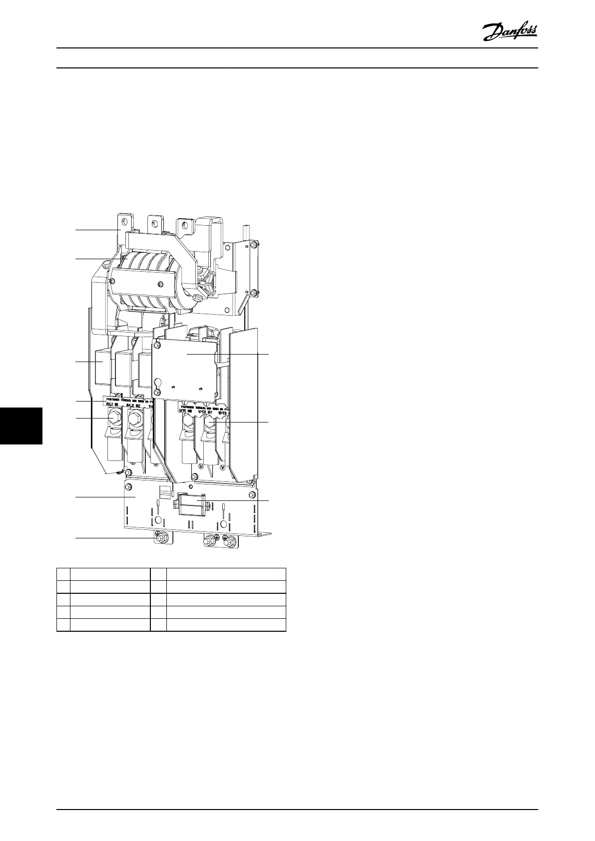
The AC input busbars can look dierent when the drive
includes extra input options, such as RFI lter or fuses.
Illustration 10.4 shows the AC input busbars with both RFI
lter and AC fuses, and Illustration 10.5 shows the AC input
busbars with no options.
1 AC input busbar 6 Power terminal mounting plate
2 RFI lter (optional) 7 Nut
3 AC fuse (optional) 8 EMC shield
4 R/S/T terminal label 9 Motor terminal
5 Mains input terminal 10 Mixing fan
Illustration 10.4 AC Input Busbars with RFI Filter and Fuses
1. Remove the air bae by removing 4 screws (T25)
and 2 nuts (13 mm).
2. The next step diers based on the input options
present in the drive. Select the appropriate
procedure for the drive:
2a No options.
2b AC fuses only.
2c RFI lter only.
2d AC fuses and RFI lter.
10.2.5.1 No Options
1. Remove 3 nuts (10 mm) at the top of the AC
input busbars, 1 per phase.
2. Remove 6 nuts (13 mm) at the bottom of the AC
input busbars, 2 per phase.
3. Remove the busbars from the drive.
Reinstall in reverse order of this procedure. Tighten
hardware according to chapter 14.1 Fastener Torque Ratings.
10.2.5.2 AC Fuses Only
1. Remove AC fuses by removing 6 nuts (13 mm), 1
at each end of 3 fuses.
2. Remove 3 nuts (10 mm) at the top of the AC
input busbars, 1 per phase.
3. Remove the AC input busbars.
Reinstall in reverse order of this procedure. Tighten
hardware according to chapter 14.1 Fastener Torque Ratings.
10.2.5.3 RFI Filter Only
1. Remove 3 nuts (10 mm) at the top of the RFI
lter, 1 per bus phase.
2. Remove 6 nuts (13 mm) at the bottom of the RFI
lter, 2 per phase.
3. Remove 4 screws (T20) connecting the RFI lter
to the side channels of the drive.
4. Remove the RFI lter and unplug the RFI cable
from MK100 on the printed circuit card assembly.
Reinstall in reverse order of this procedure. Tighten
hardware according to chapter 14.1 Fastener Torque Ratings.
10.2.5.4 AC Fuses and RFI Filter
1. Remove AC fuses by removing 6 nuts (13 mm), 1
at each end of 3 fuses.
2. Remove 3 nuts (10 mm) from the top of the RFI
lter, 1 per phase.
3. Remove 4 screws (T20) connecting the RFI lter
to the side channels of the drive.
4. Remove the RFI lter and unplug the RFI cable
from MK100 on the printed circuit card assembly.
Reinstall in reverse order of this procedure. Tighten
hardware according to chapter 14.1 Fastener Torque Ratings.
D1h/D3h/D5h/D6h/J8 Drive Di...
VLT
®
FC Series, D1h–D8h, Da2/Db2/Da4/Db4, E1h–E4h, J8/J9
136 Danfoss A/S © 02/2019 All rights reserved. MG94A502
1010
 Loading...


