The display is divided into three sections:
Top section (a)
Shows the status when in status mode or up to two
variables when not in status mode and in the case of
alarm/warning.
The number of the active set-up (selected as the active
set-up in 0-10 Active Set-up) is shown. When programming
in another set-up than the active set-up, the number of
the set-up being programmed appears to the right in
brackets.
Middle section (b)
Shows up to five variables with related unit, regardless of
status. In the event of an alarm/warning, the warning is
shown instead of the variables.
It is possible to toggle between three status readout
displays by pressing [Status].
Operating variables with different formatting are shown in
each status screen.
Several values or measurements can be linked to each of
the displayed operating variables. The values/
measurements to be displayed can be defined via
parameters 0–20, 0–21, 0–22, 0–23, and 0–24.
Each value/measurement readout parameter selected in
parameters 0–20 to 0–24 has its own scale and number of
digits after a possible decimal point. Larger numeric values
are displayed with few digits after the decimal point.
Ex.: Current readout
5.25 A; 15.2 A 105 A.
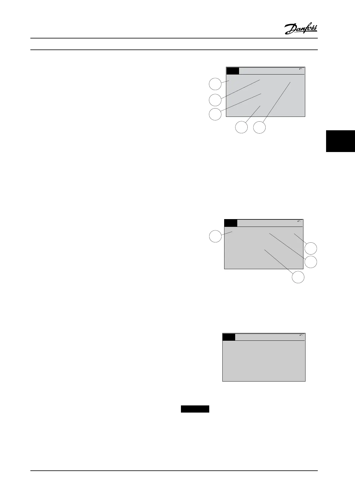
Status display I
This readout state is standard after startup or initialization.
Press [Info] to obtain information about the value/
measurement linked to the displayed operating variables
(1.1, 1.2, 1.3, 2, and 3).
See the operating variables shown in the display in
Figure 5.2. 1.1, 1.2 and 1.3 are shown in small size. 2 and 3
are shown in medium size.
1.1
2
3
1.3
1.2
130BP041.10
799 RPM
Auto Remote Ramping
1 (1)
36.4 kW7.83 A
0.000
53.2%
Status
Figure 5.2 Status Display I - Operating Variables
Status display II
See the operating variables (1.1, 1.2, 1.3, and 2) shown in
the display in Figure 5.3.
In the example, speed, motor current, motor power, and
frequency are selected as variables in the first and second
lines.
1.1, 1.2 and 1.3 are shown in small size. 2 is shown in large
size.
1.1
1.2
2
1.3
130BP062.10
207RPM
Auto Remote Running
1 (1)
24.4 kW5.25A
6.9Hz
Status
Figure 5.3 Status Display II - Operating Variables
Status display III
This state displays the event and action of the smart logic
control.
130BP063.10
778 RPM
Auto Remote Running
1 (1)
4.0 kW0.86 A
State: 0 o 0 (o)
When: -
Do: -
Status
Figure 5.4 Status Display III - Operating Variables
NOTICE!
Status display III is not available on the filter LCP.
User Interface Instruction Manual
MG37A222 Danfoss A/S © Rev. 2014-02-07 All rights reserved. 45
5 5
 Loading...


