Analog inputs
Number of analog inputs 2
Terminal number 53, 54
Modes Voltage or current
Mode select Switch S201 and switch S202
Voltage mode Switch S201/switch S202 = OFF (U)
Voltage level 0 to + 10 V (scaleable)
Input resistance, R
i
approx. 10 kΩ
Max. voltage ± 20 V
Current mode Switch S201/switch S202 = ON (I)
Current level 0/4 to 20 mA (scaleable)
Input resistance, R
i
approx. 200 Ω
Max. current 30 mA
Resolution for analog inputs 10 bit (+ sign)
Accuracy of analog inputs Max. error 0.5% of full scale
Bandwidth 200 Hz
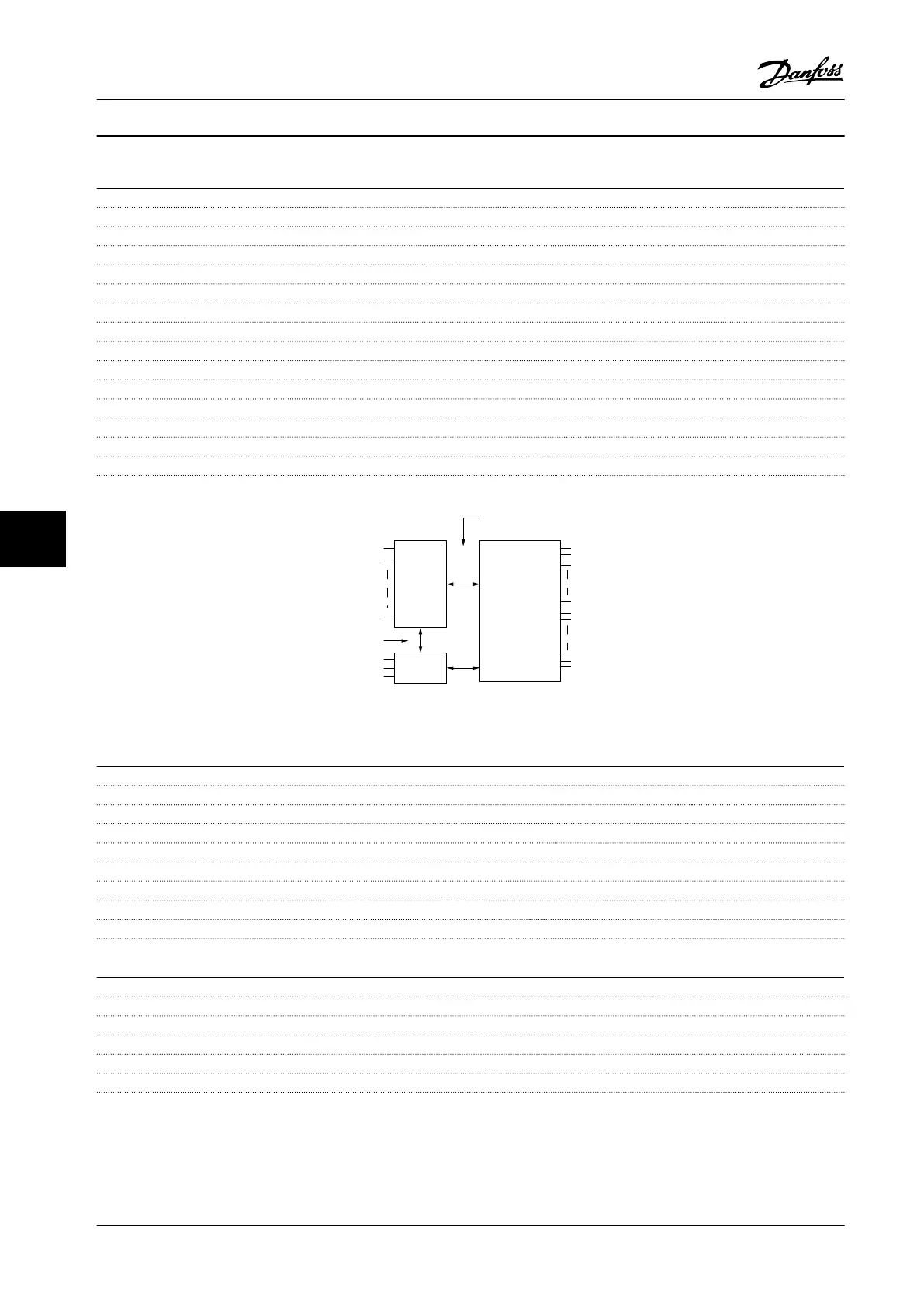
The analog inputs are galvanically isolated from the supply voltage (PELV) and other high-voltage terminals.
Mains
Functional
isolation
PELV isolation
Motor
DC-Bus
High
voltage
Control
+24V
RS485
18
37
130BA117.10
Figure 8.13
Pulse inputs
Programmable pulse inputs 2
Terminal number pulse 29, 33
Max. frequency at terminal, 29, 33 110 kHz (push-pull driven)
Max. frequency at terminal, 29, 33 5 kHz (open collector)
Min. frequency at terminal 29, 33 4 Hz
Voltage level see chapter 8.3.1 Digital inputs
Maximum voltage on input 28 V DC
Input resistance, R
i
approx. 4 kΩ
Pulse input accuracy (0.1–1 kHz) Max. error: 0.1% of full scale
Analog output
Number of programmable analog outputs 1
Terminal number 42
Current range at analog output 0/4–20 mA
Max. resistor load to common at analog output 500 Ω
Accuracy on analog output Max. error: 0.8% of full scale
Resolution on analog output 8 bit
The analog output is galvanically isolated from the supply voltage (PELV) and other high-voltage terminals.
Specications
VLT
®
AutomationDrive FC 302 Low Harmonic Drive
132–630 kW
96 Danfoss A/S © Rev. 04/2015 All rights reserved. MG37A322
88
 Loading...


