7.4 Warning and Alarm Denitions - Filter (Left LCP)
NOTICE!
This section covers warnings and alarms on the lter side LCP. For warning and alarms for the adjustable frequency
drive, see chapter 7.3 Warnings and Alarm Denitions - Adjustable Frequency Drive
A warning or an alarm is signaled by the relevant LED on the front of the lter and indicated by a code on the display. A
warning remains active until its cause is no longer present. Under certain circumstances, operation of the unit may still be
continued. Warning messages may be critical, but are not necessarily so.
In the event of an alarm, the unit will have tripped. Alarms must be reset to restart operation once their cause has been
rectied.
This may be done in four ways:
1. By pressing [Reset].
2. Via a digital input with the “Reset” function.
3. Via serial communication/optional serial communication bus.
4. By resetting automatically using the [Auto Reset] function.
NOTICE!
After a manual reset pressing [Reset], press [Auto On] or [Hand On] to restart the unit.
If an alarm cannot be reset, the reason may be that its cause has not been rectied, or the alarm is trip-locked (see also
Table 7.2). Alarms that are trip-locked oer additional protection, meaning that the line power supply must be switched o
before the alarm can be reset. After being switched back on, the unit is no longer blocked and may be reset as described
above once the cause has been rectied.
Alarms that are not trip-locked can also be reset using the automatic reset function in parameter 14-20 Reset Mode (Warning:
automatic wake-up is possible). If a warning and alarm is marked against a code in Table 7.2, either a warning occurs before
an alarm, or it can be specied whether it is a warning or an alarm that is to be displayed for a given fault.
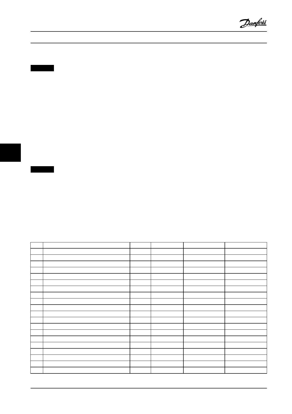
No. Description Warning Alarm/Trip Alarm/Trip Lock Parameter Reference
1 10 Volts low X
2 Live zero error (X) (X) 6-01
4 Mains phase loss X
5 DC link voltage high X
6 DC link voltage low X
7 DC overvoltage X X
8 DC undervoltage X X
13 Overcurrent X X X
14 Ground fault X X X
15 Hardware mismatch X X
16 Short-circuit X X
17 Control word timeout (X) (X) 8-04
23 Internal fan fault X
24 External fan fault X 14-53
29 Heatsink temp X X X
33 Inrush fault X X
34 Fieldbus fault X X
35 Option fault X X
38 Internal fault
39 Heatsink sensor X X
Status Messages
VLT
®
AutomationDrive FC 302 Low Harmonic Drive
132–630 kW
78 Danfoss A/S © Rev. 04/2015 All rights reserved. MG37A322
77
 Loading...


