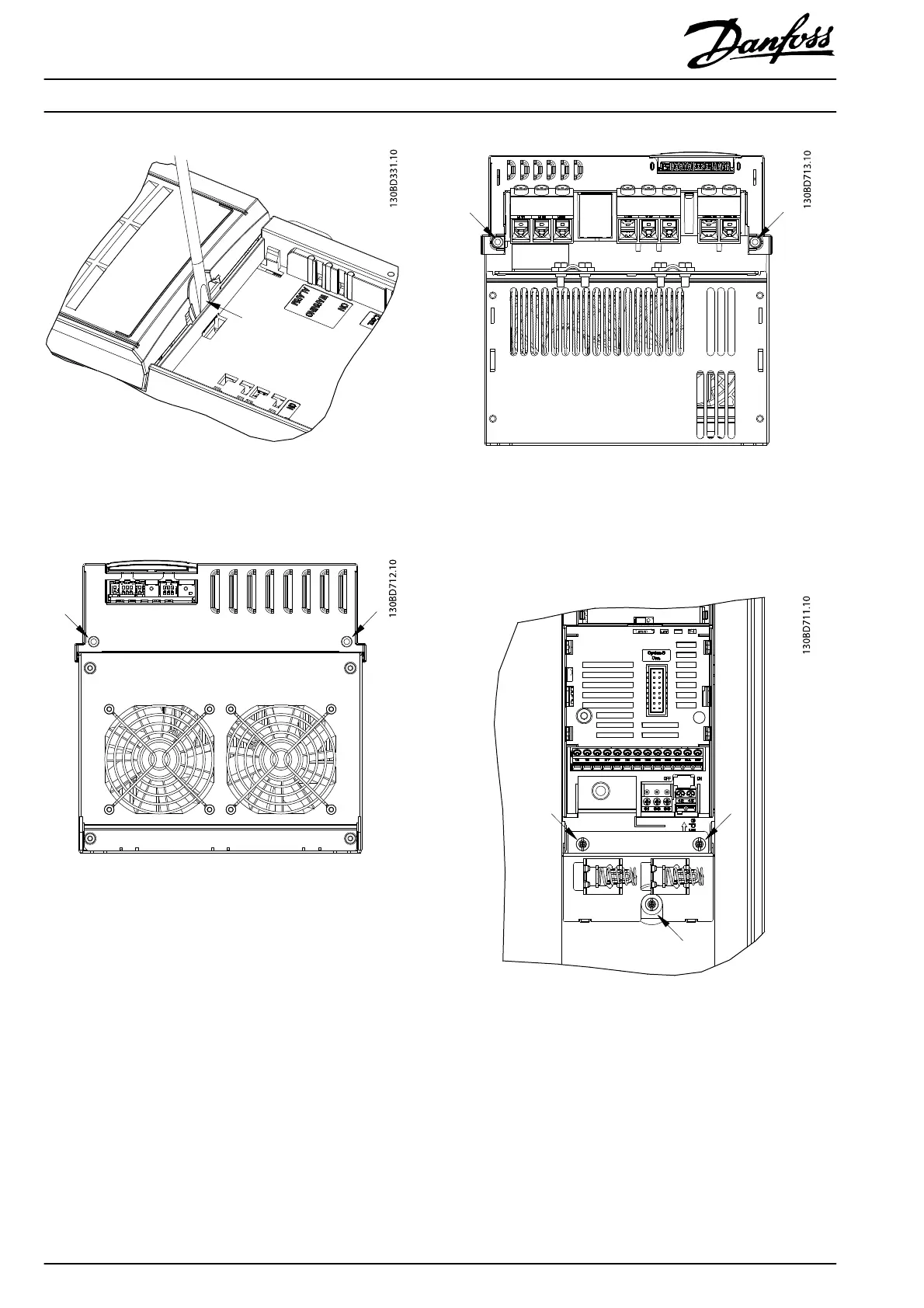
Illustration 1.1 Remove Plastic Cover
3. Remove 4 screws (T20, M4x8) that fasten the front
cover to the base plate.
Illustration 1.2 Location of Screws on Top Plate, Example
(Enclosure Type J6)
Illustration 1.3 Location of Screws on Bottom Plate, Example
(Enclosure Type J6)
4. Remove the 2 (for enclosure type J7) or 3 (for
enclosure type J6) screws on the I/O decoupling
plate.
Illustration 1.4 Screws on the I/O Decoupling Plate for Enclosure
Type J6
Installation Instructions
Front Cover
VLT
®
AutomationDrive FC 360
2
Danfoss A/S © Rev. 2014-01-17 All rights reserved. MI06R102

 Loading...


