8.2.7 Control Processing
See Active/Inactive Parameters in Dierent Drive Control Modes in the programming guide for an overview of which control
conguration is available for your application, depending on selection of AC motor or PM motor.
8.2.7.1
Control Structure in VVC
+
+
_
+
_
Cong. mode
Ref.
Process
P 1-00
High
+f max.
Low
-f max.
P 4-11
Motor speed
low limit (RPM)
P 4-12
Motor speed
low limit (Hz)
P 4-13
Motor speed
high limit (RPM)
P 4-14
Motor speed
high limit (Hz)
Motor
controller
Ramp
Speed
PID
P 7-20 Process feedback
1 source
P 7-22 Process feedback
2 source
P 7-00 Speed PID
feedback source
P 1-00
Cong. mode
P 4-19
Max. output freq.
-f max.
Motor
controller
P 4-19
Max. output freq.
+f max.
P 3-**
P 7-0*
130BA055.10
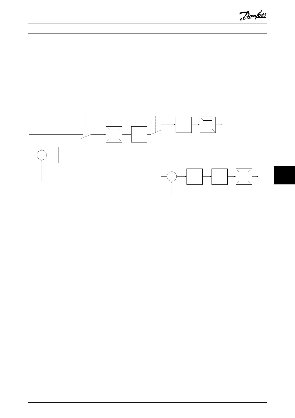
Illustration 8.8 Control Structure in VVC
+
Open-loop and Closed-loop Congurations
In Illustration 8.8, the resulting reference from the reference handling system is received and fed through the ramp limitation
and speed limitation before being sent to the motor control. The output of the motor control is then limited by the
maximum frequency limit.
Parameter 1-01 Motor Control Principle is set to [1] VVC
+
and parameter 1-00 Conguration Mode is set to [0] Speed open loop.
If parameter 1-00 Conguration Mode is set to [1] Speed closed loop, the resulting reference is passed from the ramp
limitation and speed limitation into a speed PID control. The speed PID control parameters are located in parameter group
7-0* Speed PID Ctrl. The resulting reference from the speed PID control is sent to the motor control limited by the frequency
limit.
Select [3] Process in parameter 1-00 Conguration Mode to use the process PID control for closed-loop control of, for example,
speed or pressure in the controlled application. The process PID parameters are in parameter groups 7-2* Process Ctrl. Feedb
and 7-3* Process PID Ctrl.
8.2.7.2
Internal Current Control in VVC
+
Mode
When the motor torque exceeds the torque limits set in parameter 4-16 Torque Limit Motor Mode, parameter 4-17 Torque Limit
Generator Mode, and parameter 4-18 Current Limit, the integral current limit control is activated.
When the drive is at the current limit during motor operation or regenerative operation, it tries to get below the preset
torque limits as quickly as possible without losing control of the motor.
Basic Operating Principles ... Design Guide
MG06K102 Danfoss A/S © 03/2019 All rights reserved. 67
8 8
 Loading...


