Minimum speed limit
Parameter 4-12 Motor Speed Low Limit [Hz] sets the
minimum output speed that the drive can provide.
Maximum speed limit
Parameter 4-14 Motor Speed High Limit [Hz] or
parameter 4-19 Max Output Frequency sets the maximum
output speed that the drive can provide.
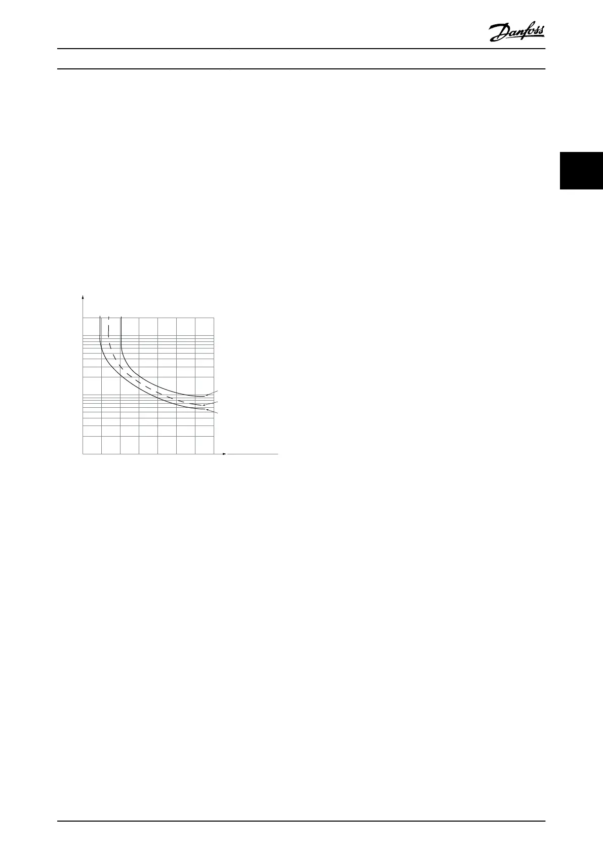
ETR (electronic thermal relay)
The drive ETR function measures the actual current, speed,
and time to calculate motor temperature. The function also
protects the motor from being overheated (warning or
trip). An external thermistor input is also available. ETR is
an electronic feature that simulates a bimetal relay based
on internal measurements. The characteristic is shown in
Illustration 3.1.
1.21.0 1.4
30
10
20
100
60
40
50
1.81.6 2.0
2000
500
200
400
300
1000
600
t [s]
175ZA052.12
f
OUT
= 2 x f
M,N
f
OUT
= 0.2 x f
M,N
f
OUT
= 1 x f
M,N
(par. 1-23)
I
MN
(par. 1-24)
I
M
Illustration 3.1 ETR
The X-axis shows the ratio between I
motor
and I
motor
nominal. The Y-axis shows the time in seconds before the
ETR cuts o and trips the drive. The curves show the
characteristic nominal speed at twice the nominal speed
and at 0.2 x the nominal speed.
At lower speed, the ETR cuts o at lower heat due to less
cooling of the motor. In that way, the motor is protected
from being overheated even at low speed. The ETR feature
calculates the motor temperature based on actual current
and speed. The calculated temperature is visible as a
readout parameter in parameter 16-18 Motor Thermal.
3.3.4 Mains Drop-out
During a mains drop-out, the drive keeps running until the
DC-link voltage drops below the minimum stop level. The
minimum stop level is typically 15% below the lowest
rated supply voltage. The mains voltage before the drop-
out and the motor load determine how long it takes for
the drive to coast.
The drive can be congured (parameter 14-10 Mains Failure)
to dierent types of behavior during mains drop-out:
•
Trip lock once the DC-link is exhausted.
•
Coast with ying start whenever mains return
(parameter 1-73 Flying Start).
•
Kinetic back-up.
•
Controlled ramp down.
Flying start
This selection makes it possible to catch a motor that is
spinning freely due to a mains drop-out. This option is
relevant for centrifuges and fans.
Kinetic back-up
This selection ensures that the drive runs as long as there
is energy in the system. For short mains drop-out, the
operation is restored after mains return, without bringing
the application to a stop or losing control at any time.
Several variants of kinetic back-up can be selected.
Congure the behavior of the drive at mains drop-out in
parameter 14-10 Mains Failure and parameter 1-73 Flying
Start.
3.3.5 Automatic Restart
The drive can be programmed to restart the motor
automatically after a minor trip, such as momentary power
loss or uctuation. This feature eliminates the need for
manual resetting and enhances automated operation for
remotely controlled systems. The number of restart
attempts and the duration between attempts can be
limited.
3.3.6 Full Torque at Reduced Speed
The drive follows a variable V/Hz curve to provide full
motor torque even at reduced speeds. Full output torque
can coincide with the maximum designed operating speed
of the motor. This drive diers from variable torque drives
and constant torque drives. Variable torque drives provide
reduced motor torque at low speed. Constant torque
drives provide excess voltage, heat, and motor noise at less
than full speed.
3.3.7 Frequency Bypass
In some applications, the system can have operational
speeds that create a mechanical resonance. This
mechanical resonance can generate excessive noise and
possibly damage mechanical components in the system.
The drive has 4 programmable bypass-frequency
bandwidths. The bandwidths allow the motor to step over
speeds that induce system resonance.
Product Overview and Featur... Design Guide
MG06K102 Danfoss A/S © 03/2019 All rights reserved. 11
3 3

 Loading...


