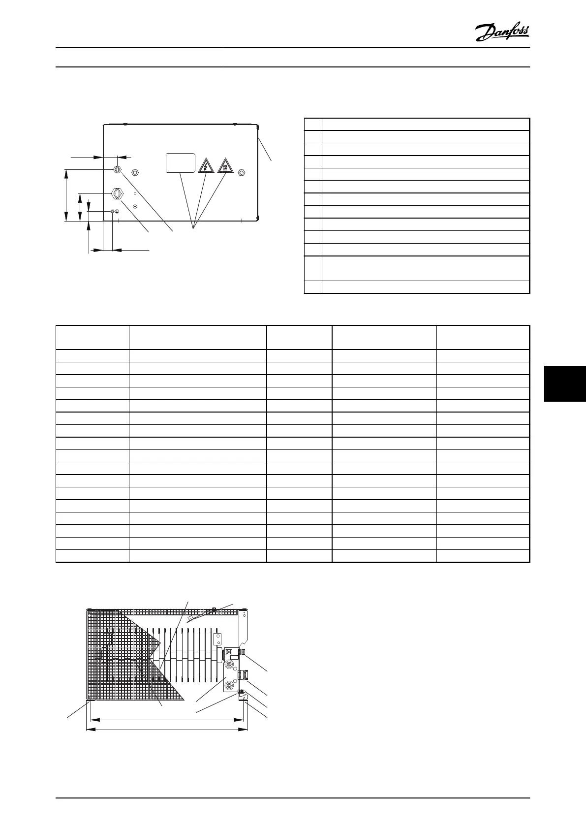
9.7.9 Figure 9 - 917CM15
175Uxxxx
6
8
3 4
30 [ 1.2 ]
45 [1.8]
160 [6.3]
85 [3.3]
30 [1.2]
130BD246.10
Illustration 9.44 IP20, Side View, Right
1 Resistor
2
Terminal board, see Illustration 9.47
3 Cable gland for load cables
4 Cable gland M16 temperature switch cable
5 Grounding bolt M6
6 Name plate/warning signs
7 Front cover IP20
8 Rear cover IP20
9 Top cover IP20
10
Temperature switch 260 °C (NC)
11 Load connection, 2x bolt M8
12 Auxiliary connection for temperature switch, porcelain
clamp 2.5 mm
2
13 4x fixing hole Ø 9 mm
Table 9.17 Legend to Illustration 9.44 to Illustration 9.47
Danfoss P/N Type code
Resistance [Ω]
Cable gland type for load
terminals
Weight [kg]
175u3067 MCE101C9R10P9K00E20BAW 9.1 M40 21
175u3079 MCE101C4R70P9K00E20BAW 4.7 M40 21
175u3200 MCE101C27R0P10K0E20BAW 27.0 M25 22
175u3203 MCE101C19R0P10K0E20BAW 19.0 M25 20
175u3231 MCE101C5R50P7K00E20BAW 5.5 M32 19
175u3232 MCE101C11R0P7K00E20BAW 11 M25 19
175u3233 MCE101C5R70P6K00E20BAW 5.7 M25 19
175u3234 MCE101C5R70P8K00E20BAW 5.7 M25 20
175u3235 MCE101C3R50P9K00E20BAW 3.5 M25 21
175u3237 MCE101C28R0P6K00E20BAW 28 M25 19
175u3238 MCE101C22R0P8K00E20BAW 22 M25 20
175u3239 MCE101C38R0P6K00E20BAW 38 M25 19
175u3240 MCE101C31R0P8K00E20BAW 31 M25 20
175u3242 MCE101C52R0P6K00E20BAW 52 M25 19
175u3243 MCE101C42R0P8K00E20BAW 42 M25 20
175u3244 MCE101C31R0P10K0E20BAW 31 M25 22
175u3245 MCE101C7R00P7K00E20BAW 7 M32 20
Table 9.18 Mechanical Dimensions
1
2
Thermocontact
260 °C (NC)
260°C
502 [ 19.8 ]
530 [ 20.9 ]
2
3
4
5
7
10
13 13
1
5
130BD252.10
Illustration 9.45 IP20, Front View
Specifications Design Guide
MG90O202 Danfoss A/S © Rev. 05/2014 All rights reserved. 105
9 9

 Loading...

