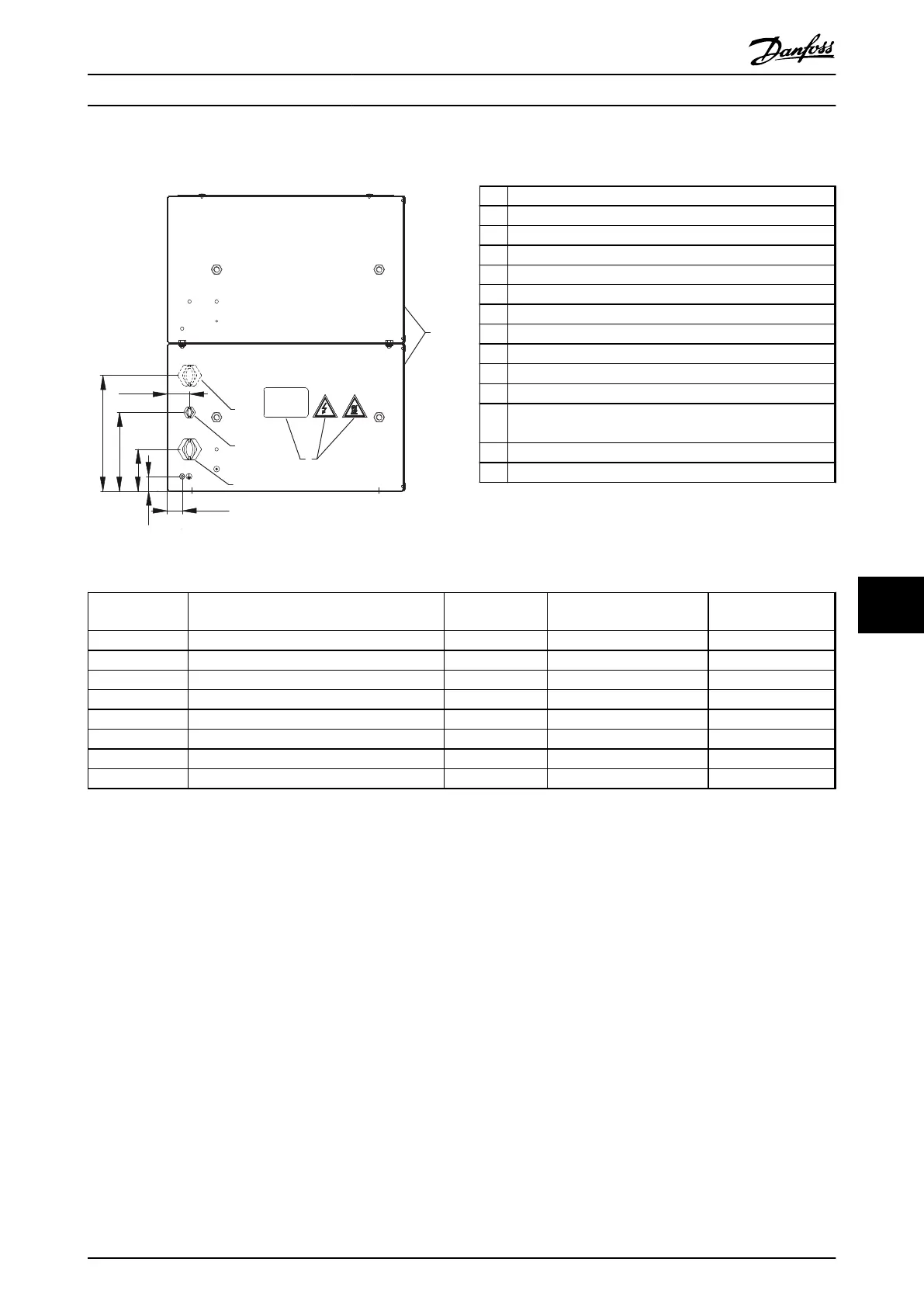
9.7.11 Figure 11 - 917CM25
8
6
14
4
3
30 [1.2]
30 [1.2]
85 [3.3]
160 [6.3]
235 [9.3]
45 [1.8]
175Uxxxx
130BD261.10
Illustration 9.54 IP20, Side View, Right
1 Resistor
2
Terminal board, see Illustration 9.57
3 Cable gland for load cables
4 Cable gland M16 temperature switch cable
5 Grounding bolt M6
6 Name plate/warnings signs
7 Front cover IP20
8 Rear cover IP20
9 Top cover IP20
10
Temperature switch 260 °C (NC)
11 Load connection, 2x bolt M8
12 Auxiliary connection for temperature switch, porcelain
clamp 2.5 mm
2
13 4x fixing hole Ø 9 mm
14 Second cable gland. Not in use
Table 9.21 Legend to Illustration 9.54 to Illustration 9.58
Danfoss P/N Type code
Resistance [Ω]
Cable gland type for load
terminals
Weight [kg]
175u3078 MCE101C5R00P16K0E20BAW 5.0 2xM25 35
175u3082 MCE101C4R00P20K0E20BAW 4.0 2xM32 37
175u3088 MCE101C2R70P16K0E20BAW 2.7 2xM32 35
175u3091 MCE101C2R10P20K0E20BAW 2.1 2xM40 37
175u3202 MCE101C22K0P17K0E20BAW 22.0 M25 35
175u3207 MCE101C14R0P17K0E20BAW 14.0 M32 35
175u3210 MCE101C12R0P17K0E20BAW 12.0 M32 35
175u3227 MCE101C2R80P17K0E20BAW 2.8 M40 35
Table 9.22 Mechanical Dimensions
Specifications Design Guide
MG90O202 Danfoss A/S © Rev. 05/2014 All rights reserved. 109
9 9

 Loading...

