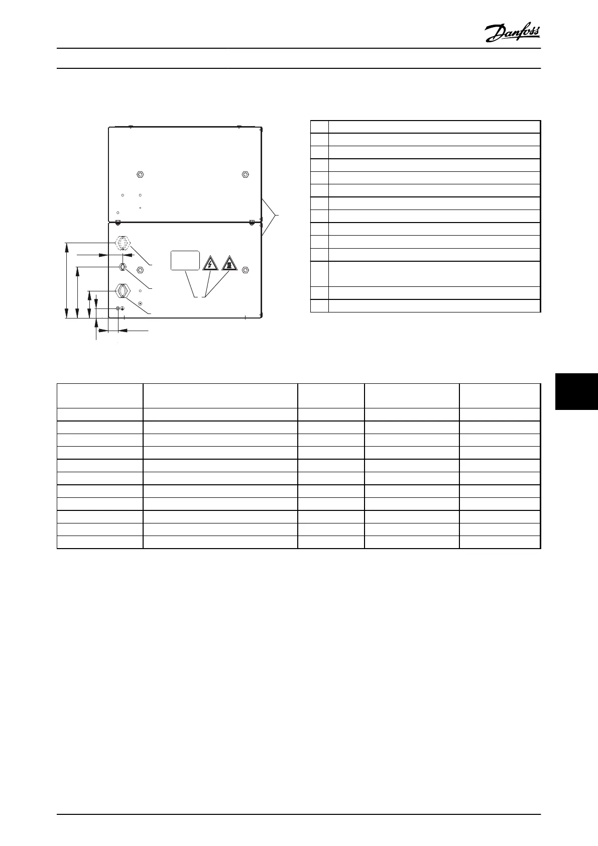
9.7.12 Figure 12 - 917CM27
8
6
14
4
3
30 [1.2]
30 [1.2]
85 [3.3]
160 [6.3]
235 [9.3]
45 [1.8]
175Uxxxx
130BD261.10
Illustration 9.59 IP20, Side View, Right
1 Resistor
2
Terminal board, see Illustration 9.62
3 Cable gland for load cables
4 Cable gland M16 temperature switch cable
5 Grounding bolt M6
6 Name plate/warning signs
7 Front cover IP20
8 Rear cover IP20
9 Top cover IP20
10
Temperature switch 260 °C (NC)
11 Load connection, 2x bolt M8
12 Auxiliary connection for temperature switch, porcelain
clamp 2.5 mm
2
13 4x fixing hole Ø 9 mm
14 Second cable gland. Not in use.
Table 9.23 Legend to Illustration 9.59 to Illustration 9.63
Danfoss P/N Typecode
Resistance [Ω]
Cable gland type for
load terminals
Weight [kg]
175u3085 MCE101C3R30P26K0E20BAW 3.3 2xM32 45
175u3089 MCE101C2R50P32K0E20BAW 2.5 2xM50 48
175u3093 MCE101C1R70P26K0E20BAW 1.7 2xM50 45
175u3097 MCE101C1R30P32K0E20BAW 1.3 2xM50 48
175u3205 MCE101C15R5P21K0E20BAW 15.5 M32 41
175u3208 MCE101C13R5P21K0E20BAW 13.5 M32 41
175u3209 MCE101C13R5P26K0E20BAW 13.5 M32 45
175u3211 MCE101C11R0P26K0E20BAW 11.0 M32 45
175u3213 MCE101C9R50P21K0E20BAW 9.5 M32 41
175u3216 MCE101C7R00P26K0E20BAW 7.0 M40 45
175u3241 MCE101C7R00P30K0E20BAW 7.0 M40 52
Table 9.24 Mechanical Dimensions
Specifications Design Guide
MG90O202 Danfoss A/S © Rev. 05/2014 All rights reserved. 111
9 9

 Loading...

