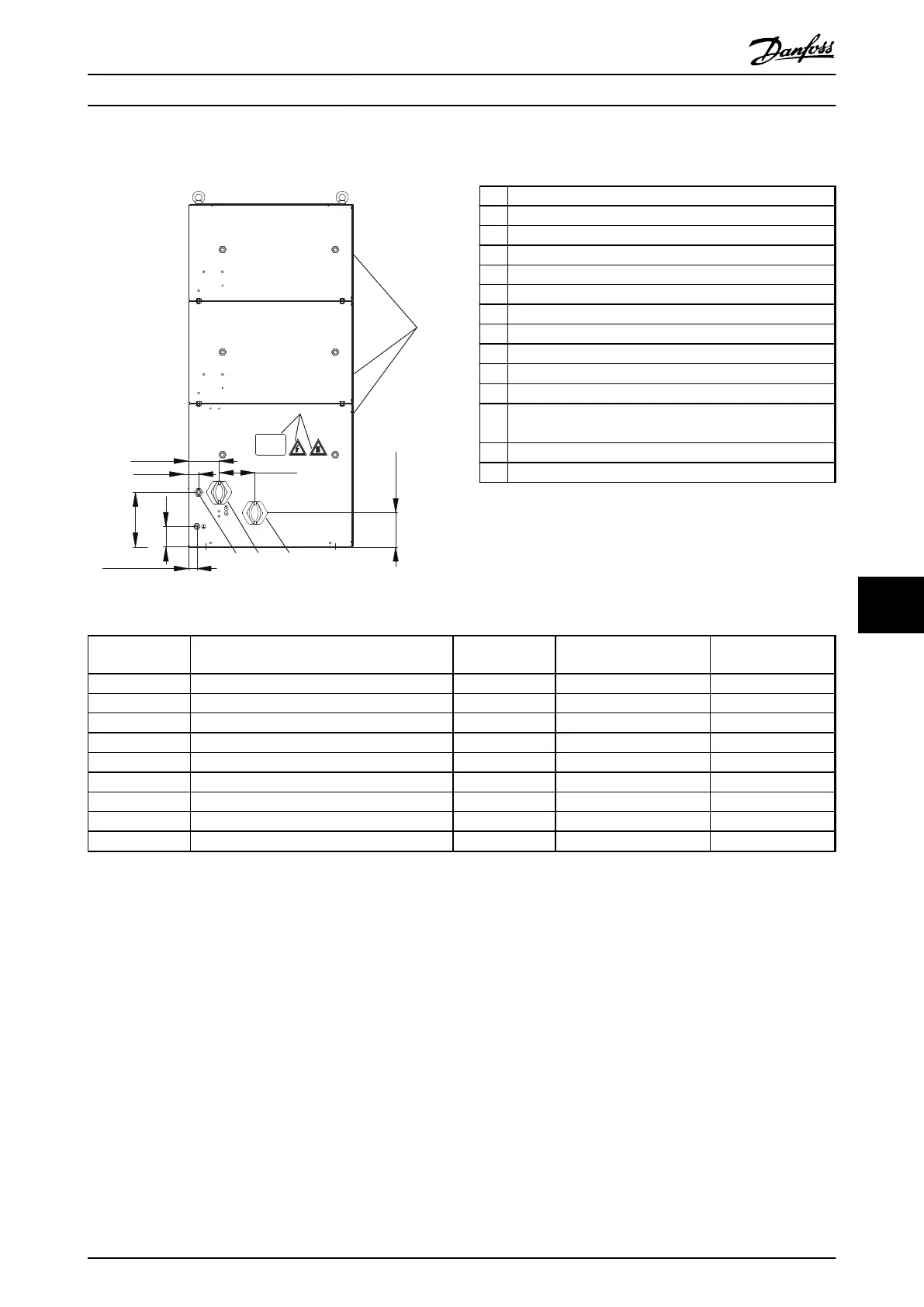
9.7.13 Figure 13 - 917CM37
130BD271.10
175Uxxxx
8
6
160 [ 6.3 ]
60 [ 2.4 ]
25 [ 1.0 ]
30 [ 1.2 ]
4
3
90 [ 3.5 ]
14
100 [ 3.9 ]
100 [ 3.9 ]
Illustration 9.64 IP20, Side View, Right
1 Resistor
2
Terminal board, see Illustration 9.67
3 Cable gland for load cables
4 Cable gland M16 temperature switch cable
5 Grounding bolt M10
6 Name plate/warning signs
7 Front cover IP20
8 Rear cover IP20
9 Top cover IP20
10
Temperature switch 260 °C (NC)
11 Load connection, 2x bolt M8
12 Auxiliary connection for temperature switch, porcelain
clamp 2.5 mm
2
13 4x fixing hole Ø 9 mm
14 Second cable gland. Not in use.
Table 9.25 Legend to Illustration 9.64 to Illustration 9.68
Danfoss P/N Type code
Resistance [Ω]
Cable gland type for load
terminals
Weight [kg]
175u3090 MCE101C2R30P36K0E20BAW 2.3 2xM50 74
175u3092 MCE101C2R00P42K0E20BAW 2.0 2xM50 78
175u3098 MCE101C1R20P36K0E20BAW 1.2 2xM50 74
175u3099 MCE101C1R10P42K0E20BAW 1.1 2xM50 78
175u3212 MCE101C11R0P36K0E20BAW 11.0 M32 74
175u3214 MCE101C9R10P42K0E20BAW 9.1 M40 78
175u3217 MCE101C7R00P36K0E20BAW 7.0 M50 74
175u3219 MCE101C5R50P36K0E20BAW 5.5 M40 74
175u3221 MCE101C4R70P42K0E20BAW 4.7 M40 78
Table 9.26 Mechanical Dimensions
Specifications Design Guide
MG90O202 Danfoss A/S © Rev. 05/2014 All rights reserved. 113
9 9

 Loading...

