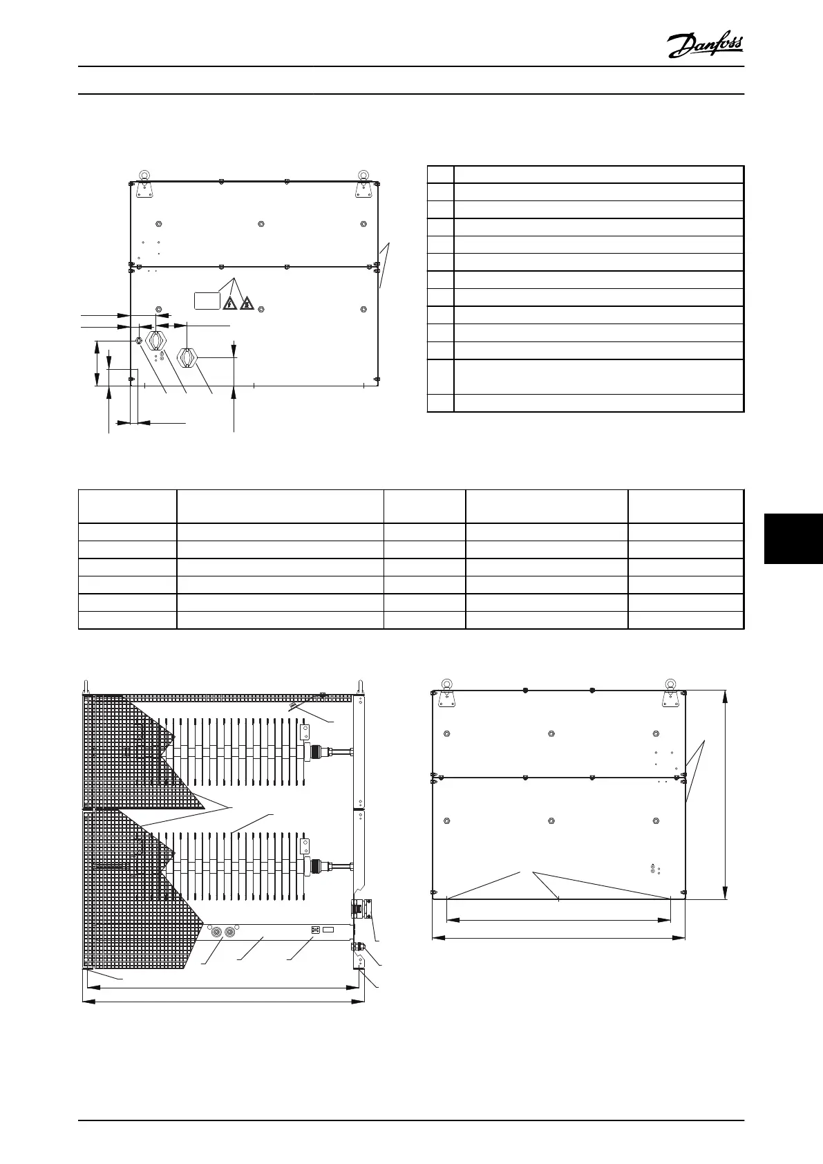
9.7.14 Figure 14 - 917CMD27
130BD276.10
175Uxxxx
8
6
160 [ 6.3 ]
60 [ 2.4 ]
25 [ 1.0 ]
30 [ 1.2 ]
4 3
90 [ 3.5 ]
3
100 [ 3.9 ]
100 [ 3.9 ]
Illustration 9.69 IP20, Side View, Right
1 Resistor
2
Terminal board, see Illustration 9.72
3 Cable gland for load cables
4 Cable gland M16 temperature switch cable
5 Grounding bolt M10
6 Name plate/warning signs
7 Front cover IP20
8 Rear cover IP20
9 Top cover IP20
10
Temperature switch 260 °C (NC)
11 Load connection, 2xbolt M8
12 Auxiliary connection for temperature switch, porcelain
clamp 2.5 mm
2
13 6xfixing hole Ø 9 mm
Table 9.27 Legend to Illustration 9.69 to Illustration 9.73
Danfoss P/N Type code
Resistance [Ω]
Cable gland type for load
terminals
Weight [kg]
175u3094 MCE101C1R60P52K0E20BAW 1.6 2xM50 90
175u3095 MCE101C1R40P60K0E20BAW 1.4 2xM50 90
175u3215 MCE101C7R40P52K0E20BAW 7.4 M40 90
175u3218 MCE101C6R10P60K0E20BAW 6.1 M50 90
175u3223 MCE101C3R70P52K0E20BAW 3.7 M50 90
175u3225 MCE101C3R30P60K0E20BAW 3.3 2xM25 90
Table 9.28 Mechanical Dimensions
The
rmocontact
260 °C (NC)
1 2
10
13
12
2
11
3/4
5
13
1
7
712 [28.0]
740 [29.1]
130BD277.10
Illustration 9.70 IP20, Front View
130BD278.10
7
770 [ 30.3 ]
870 [ 34.3 ]
13
720 [ 28.3 ]
Illustration 9.71 IP20, Side View, Left
Specifications Design Guide
MG90O202 Danfoss A/S © Rev. 05/2014 All rights reserved. 115
9 9

 Loading...

