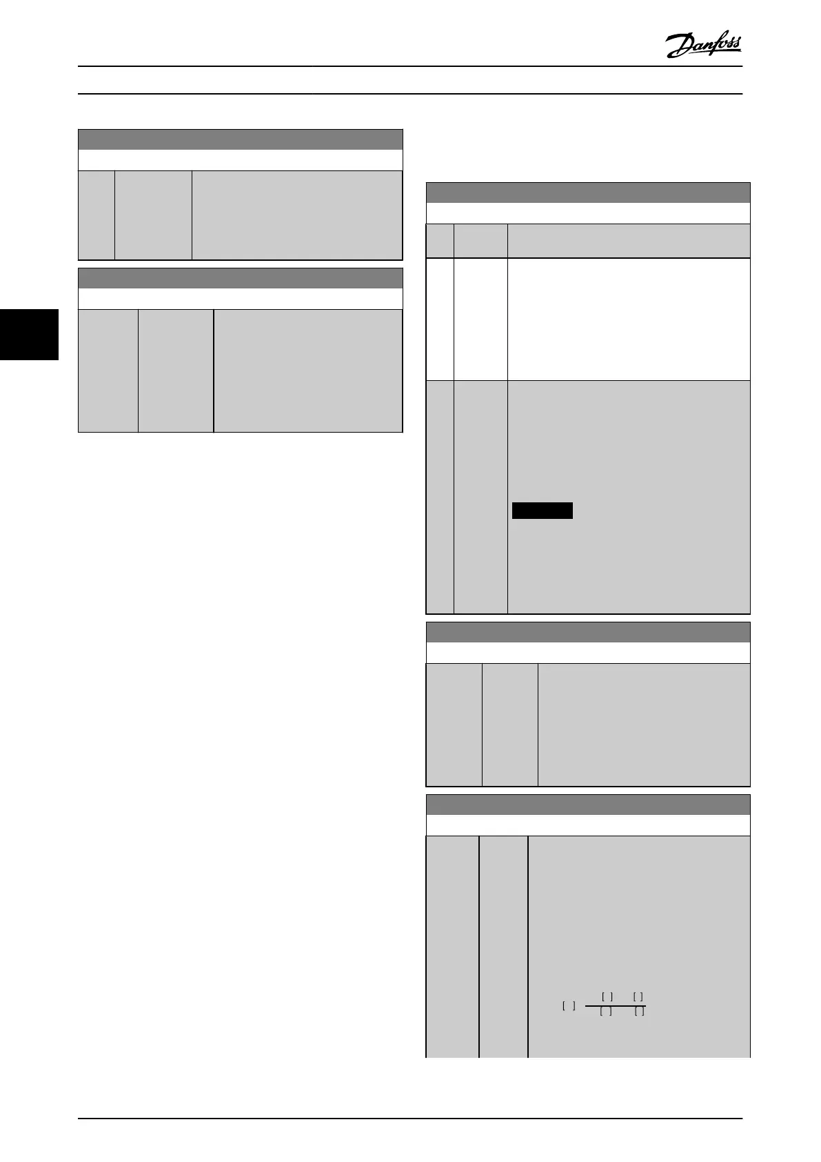
16-33 Brake Energy /2 min
Range: Function:
0 kW* [0 - 10000
kW]
View the brake power transmitted to an
external brake resistor. The mean power is
calculated on an average level based on
the selected time period within 2-13 Brake
Power Monitoring.
30-81 Brake Resistor (ohm)
Range: Function:
Size
related*
[ 0.01 -
65535.00
Ohm]
Set the brake resistor value in Ω. This
value is used for monitoring the
power to the brake resistor in
2-13 Brake Power Monitoring. This
parameter is only active in frequency
converters with an integral dynamic
brake.
5.4
Parameters for VLT
®
AutomationDrive
FC 360
2-10 Brake Function
Option: Function:
[0]
*
Off No brake resistor is installed.
[1] Resistor
brake
A brake resistor is incorporated in the system for
dissipation of surplus brake energy as heat.
Connecting a brake resistor allows a higher DC-
link voltage during braking (generating
operation). The brake resistor function is only
active in frequency converters with an integral
dynamic brake.
[2] AC brake Improves braking without using a brake resistor.
This parameter controls an overmagnetisation of
the motor when running with a generatoric load.
This function can improve the OVC-function.
Increasing the electrical losses in the motor
allows the OVC-function to increase braking
torque without exceeding the voltage limit.
NOTICE
The AC brake is not as efficient as
dynamic braking with resistor.
AC brake is for VVC
+
mode in both open
and closed loop.
2-11 Brake Resistor (ohm)
Range: Function:
Size
related*
[ 0 -
65535
Ohm]
Set the brake resistor value in Ω. This
value is used for monitoring the power to
the brake resistor. Parameter 2-11 Brake
Resistor (ohm) is only active in frequency
converters with an integral dynamic brake.
Use this parameter for values without
decimals.
2-12 Brake Power Limit (kW)
Range: Function:
Size
related*
[0.001
- 2000
kW]
Parameter 2-12 Brake Power Limit (kW) is the
expected average power dissipated in the
brake resistor over a period of 120 s. It is
used as the monitoring limit for 16-33 Brake
Energy /2 min and thereby specifies when a
warning/alarm is to be given.
To calculate parameter 2-12 Brake Power
Limit (kW), the following formula can be
used.
P
br,avg
W
=
U
br
2
V
×
t
br
s
R
br
Ω
×
T
br
s
P
br,avg
is the average power dissipated in the
brake resistor, R
br
is the resistance of the
Programming Design Guide
24 Danfoss A/S © Rev. 05/2014 All rights reserved. MG90O202
55

 Loading...

