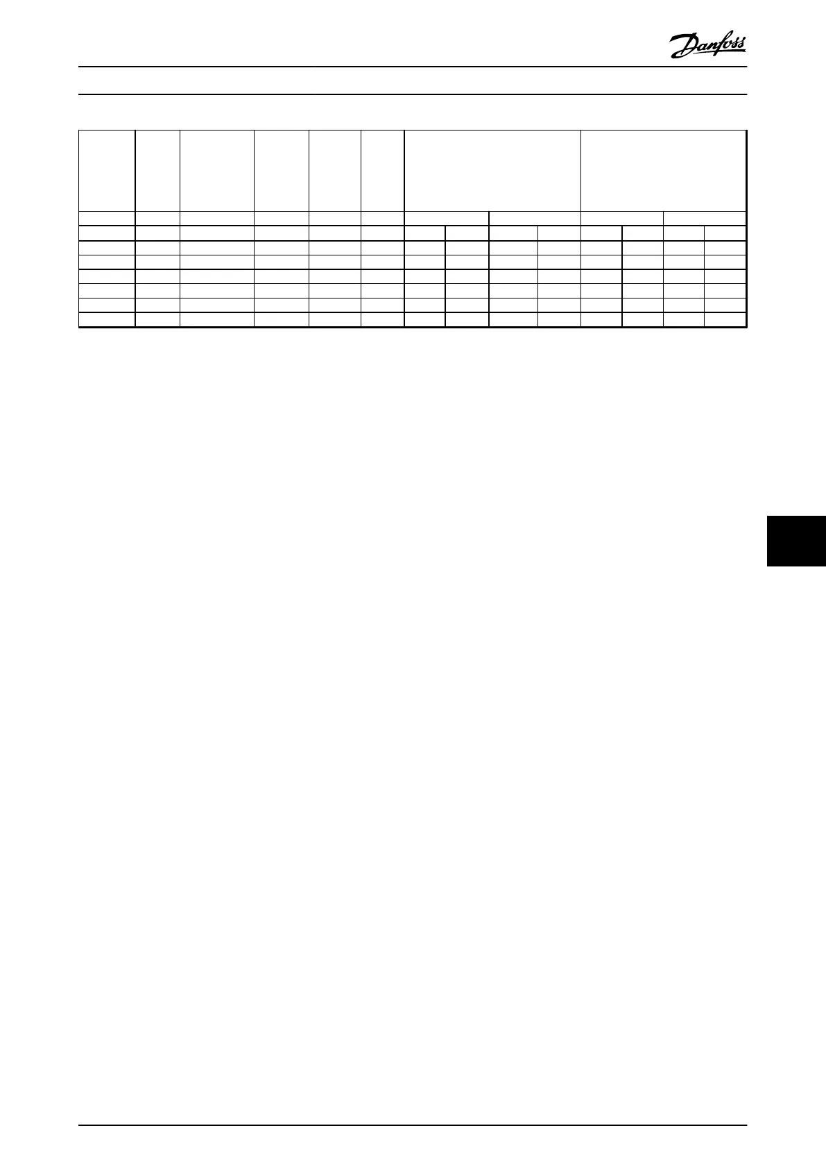
P/N
Resi-
stance
Continuous
power 100%
load
Pulse
load
power
10%
duty
cycle
1)
Pulse
load
power
40%
duty
cycle
1)
Temp.
switch
2)
3)
Terminal max wire
cross-section
Wire cross-section
4)
Temp. switch Power cables Temp. switch Power cables
[Ω]
[W] [kW] [kW] Type
[mm
2
]
[AWG]
[mm
2
]
[AWG]
[mm
2
]
[AWG]
[mm
2
]
[AWG]
175U3479 22 3200 39.9 9.9 1 4.0 12 16 6 - - - -
175U3480 22 3200 39.9 9.9 1 4.0 12 16 6 - - - -
175U3481 105 790 9.5 2.37 1 4.0 12 16 6 - - - -
175U3482 105 790 9.5 2.37 1 4.0 12 16 6 - - - -
175U3483 5.7 1700 21.1 5.27 1 4.0 12 16 6 - - - -
175U3484 5.7 1700 21.1 5.27 1 4.0 12 16 6 - - - -
Table 9.1 Electrical Data: Product Types 9xx
1) Based on reference profiles with 30 s repetition rates
2) Temperature switch type 1: 2 A. 250 V AC. Normally closed (NC). Enables at 180
°
C
3) Temperature switch type 2: 10 A. 250 V AC. Normally closed (NC). Enables at 260
°
C
4) Only for versions with fixed cables. All cables are 1000 mm unscreened cables.
Specifications Design Guide
MG90O202 Danfoss A/S © Rev. 05/2014 All rights reserved. 73
9 9

 Loading...

