3 Installation
3.1 Mechanical Installation
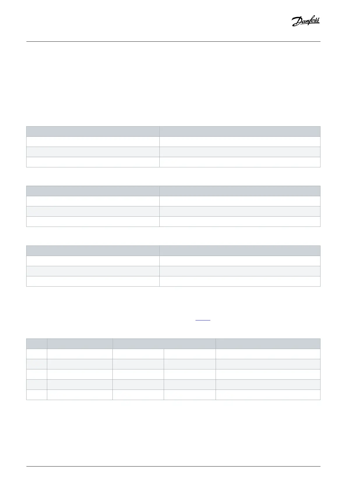
3.1.1 Cooling Capacity
Table 3: H3–H4, 400 V
Cooling capacity 400 V IP20 enclosure
4 TR/VZH028 H3
5 TR/VZH035 H3
6.5 TR/VZH044 H4
Table 4: H4–H5, 200 V
Cooling capacity 200 V IP20 enclosure
4 TR/VZH028 H4
5 TR/VZH035 H4
6.5 TR/VZH044 H5
Table 5: H5–H6, 400 V
Cooling capacity 400 V IP20 enclosure
13 TR/VZH088 H5
17 TR/VZH117 H5
26 TRVZH170 H6
3.1.2 Side-by-side Installation
The drive can be mounted side by side but requires the clearance specified in table 6 above and below for cooling.
Table 6: Clearance Required for Cooling
Power [kW (hp)] Clearance above/below [mm (in)]
Size IP protection rating 3x200–240 V 3x380–480 V
H3 IP20 – 6.0–7.5 (8.0–10) 100 (4)
H4 IP20 6.0–7.5 (8.0–10) 10 (15) 100 (4)
H5 IP20 10 (15) 18.5–22 (25–30) 100 (4)
H6 IP20 – 30(40) 200 (7.9)
Installation
Operating Guide | VLT® Compressor Drive CDS 803
AQ321748767627en-000101 / 130R0570
10 | Danfoss A/S © 2019.12

 Loading...


