3.5.9. Brake Cable
(Only standard with letter B in position 18 of typecode).
Terminal No.
Function
81, 82 Brake resistor terminals
The connection cable to the brake resistor must be shielded. Connect the shield by means of cable
clamps to the conductive back plate at the adjustable frequency drive and to the metal cabinet of
the brake resistor.
Size the brake cable cross-section to match the brake torque. See also
Brake Instructions, MI.
90.Fx.yy
and
MI.50.Sx.yy
for further information regarding safe installation.
Please note that voltages up to 1099 V DC, depending on the supply voltage, may
occur on the terminals.
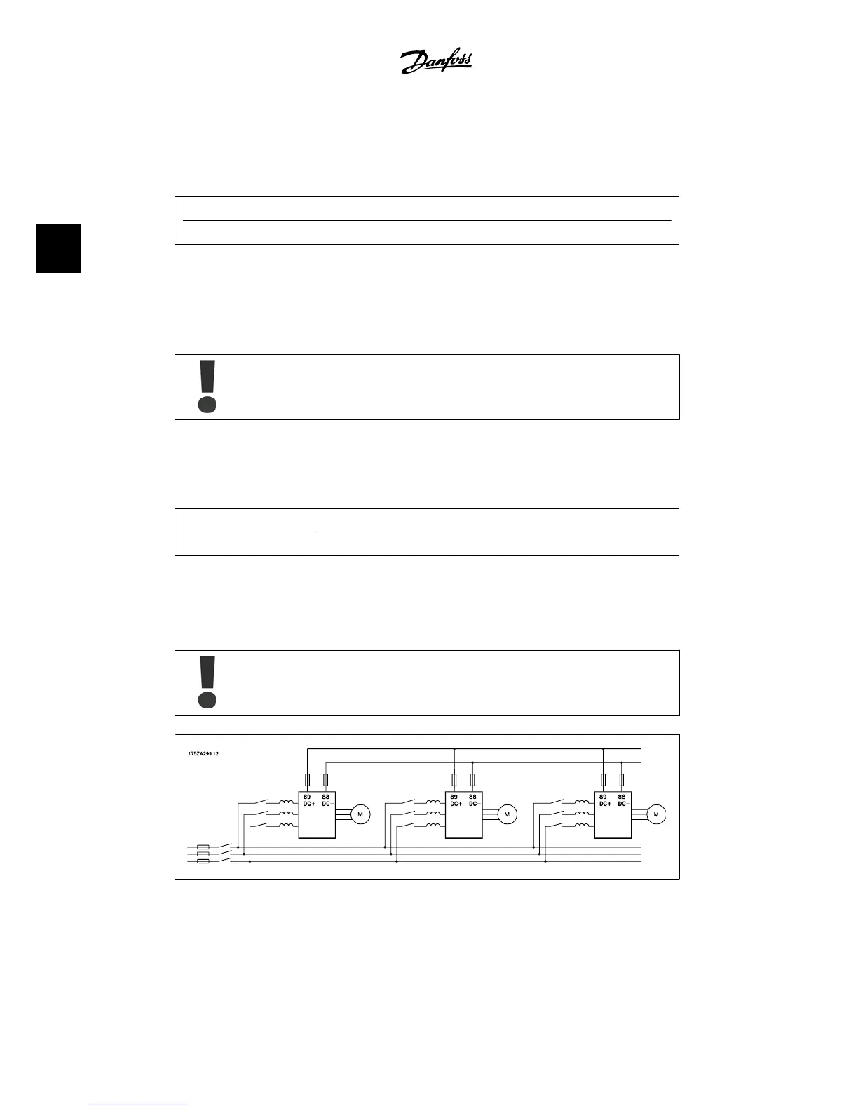
3.5.10. Load Sharing
(Only extended with letter D in position 21 of the typecode).
Terminal No.
Function
88, 89 Load sharing
The connection cable must be shielded, and the max. length from the adjustable frequency drive
to the DC bar is 81 ft [25 m].
Load sharing enables the linking of the DC intermediate circuits of several adjustable frequency
drives.
Please note that voltages up to 1099 V DC may occur on the terminals.
Load sharing calls for extra equipment. For further information, please contact Dan-
foss.
3.80: Load sharing connection
3. How to Install
VLT
®
Automation Drive FC 300
Instruction Manual High Power
58
MG.33.U1.22 - VLT
®
is a registered Danfoss trademark.
3
 Loading...


