S1 F1
F1
DC ‘-’
DC ‘+’
1739.1
805.0
765.0
1694.1
1654.1
710.0
130BB377.10
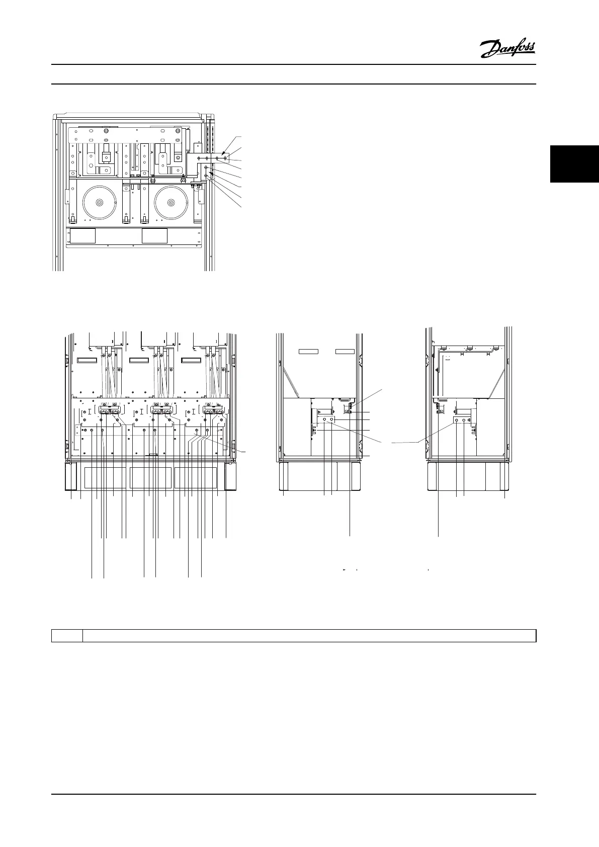
Figure 3.25 Terminal Locations - Regen Terminals - F1 and F3
Terminal locations - enclosure types F2 and F4
287.4 [11.32]
0.0 [0.00]
339.4 [13.36]
253.1 [9.96]
0.0 [0.00]
287.4 [11.32]
0.0 [0.00]
339.4 [13.36]
465.6 [18.33]
465.6 [18.33]
308.3 [12.14]
180.3 [7.10]
210.1 [8.27]
0.0 [0.00]
66.4 [2.61]
181.4 [7.14]
296.4 [11.67]
431.0 [16.97]
546.0 [21.50]
661.0 [26.03]
795.7 [31.33]
910.7 [35.85]
1025.7 [40.38]
246.1 [9.69]
294.1 [11.58]
330.1 [13.00]
574.7 [22.63]
610.7 [24.04]
658.7 [25.93]
694.7 [27.35]
939.4 [36.98]
975.4 [38.40]
1023.4 [40.29]
1059.4 [41.71]
[37.61]
1
130BA850.12
FASTENER TORQUE: MIO 19 Nm (14 FT -LB)
U/T1 96 V/T2 97 W/T3 98
FASTENER TORQUE: MIO 19 Nm (14 FT -LB)
U/T1 96 V/T2 97 W/T3 98
FASTENER TORQUE: MIO 19 Nm (14 FT -LB)
U/T1 96 V/T2 97 W/T3 98
2
3
1 Ground bar
Figure 3.26 Terminal Locations - Inverter Cabinet - F2 and F4 (Front, Left and Right Side View). The Connector Plate is 42 mm (1.65
in) below .0 level.
Mechanical Installation Instruction Manual
MG11F522 Danfoss A/S © 08/2014 All rights reserved. 25
3 3

 Loading...


