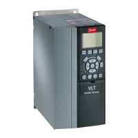
Illustration 12: Removing the Terminal Cover
The following illustration shows all the drive control terminals. Applying start (terminal 18), connection between terminals 12-27,
and an analog reference (terminal 53 or 54, and 55) make the drive run.
The digital input mode of terminal 18, 19, and 27 is set in parameter 5-00 Digital Input Mode (PNP is default value). Digital input 29
mode is set in parameter 5-03 Digital Input 29 Mode (PNP is default value).
e30bf892.10
12 20 55
18
19
27 29 42 54
45 50 53
DIGI IN
61 68 69
N
P
COMM. GND
+24 V
GND
GND
10 V OUT
10 V/20 mA IN
0/4-20 mA A OUT/DIG OUT
BUS TER.
OFF ON
DIGI IN
DIGI IN
DIGI IN
0/4-20 mA A OUT/DIG OUT
10 V/20 mA IN
Illustration 13: Control Terminals
AQ367426199594en-000101 / 130R0988 | 21Danfoss A/S © 2021.06
Installation
VLT® HVAC Drive FC 131
Operating Guide

 Loading...


