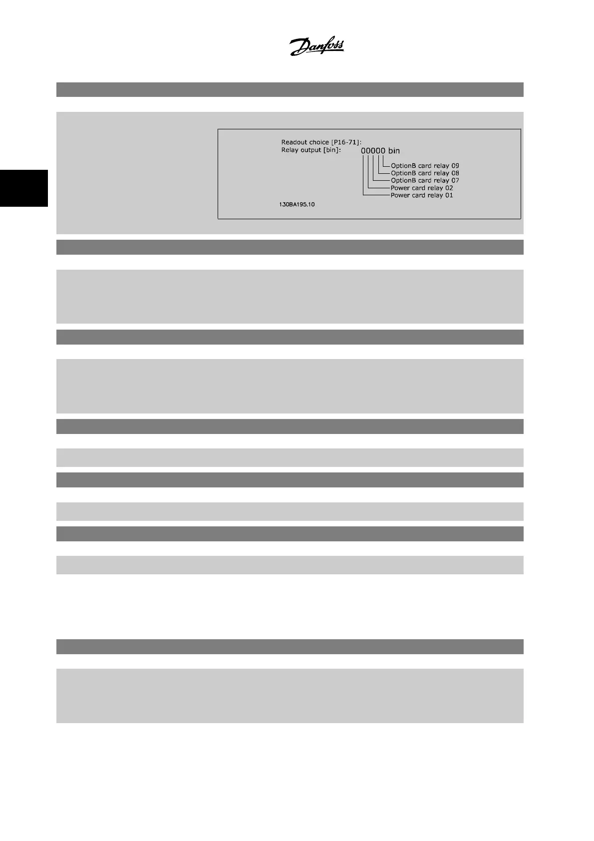
16-71 Relay Output [bin]
Range: Function:
0 N/A* [0 - 31 N/A] View the settings of all relays.
16-72 Counter A
Range: Function:
0 N/A* [-2147483648 - 2147483647 N/A] View the present value of Counter A. Counters are useful as comparator operands, see par.
13-10
Comparator Operand
.
The value can be reset or changed either via digital inputs (parameter group 5-1*) or by using an
SLC action (par.13-52
SL Controller Action
).
16-73 Counter B
Range: Function:
0 N/A* [-2147483648 - 2147483647 N/A] View the present value of Counter B. Counters are useful as comparator operands (par.13-10
Com-
parator Operand
).
The value can be reset or changed either via digital inputs (parameter group 5-1*) or by using an
SLC action (par.13-52
SL Controller Action
).
16-75 Analog In X30/11
Range: Function:
0.000 N/A* [-20.000 - 20.000 N/A] View the actual value at input X30/11 of MCB 101.
16-76 Analog In X30/12
Range: Function:
0.000 N/A* [-20.000 - 20.000 N/A] View the actual value at input X30/12 of MCB 101.
16-77 Analog Out X30/8 [mA]
Range: Function:
0.000 N/A* [0.000 - 30.000 N/A] View the actual value at input X30/8 in mA.
3.16.7 16-8* Ser. Com. Bus & Adjustable Frequency Drive Port
Parameters for reporting the BUS references and control words.
16-80 Fieldbus CTW 1
Range: Function:
0 N/A* [0 - 65535 N/A] View the two-byte control word (CTW) received from the bus master. Interpretation of the control
word depends on the serial communication bus option installed and the control word profile selected
in par.8-10
Control Profile
.
For more information, refer to the relevant serial communication bus manual.
3 Parameter Description VLT
®
HVAC Drive Programming Guide
3-158
MG.11.C6.22 - VLT
®
is a registered Danfoss trademark
3

 Loading...


