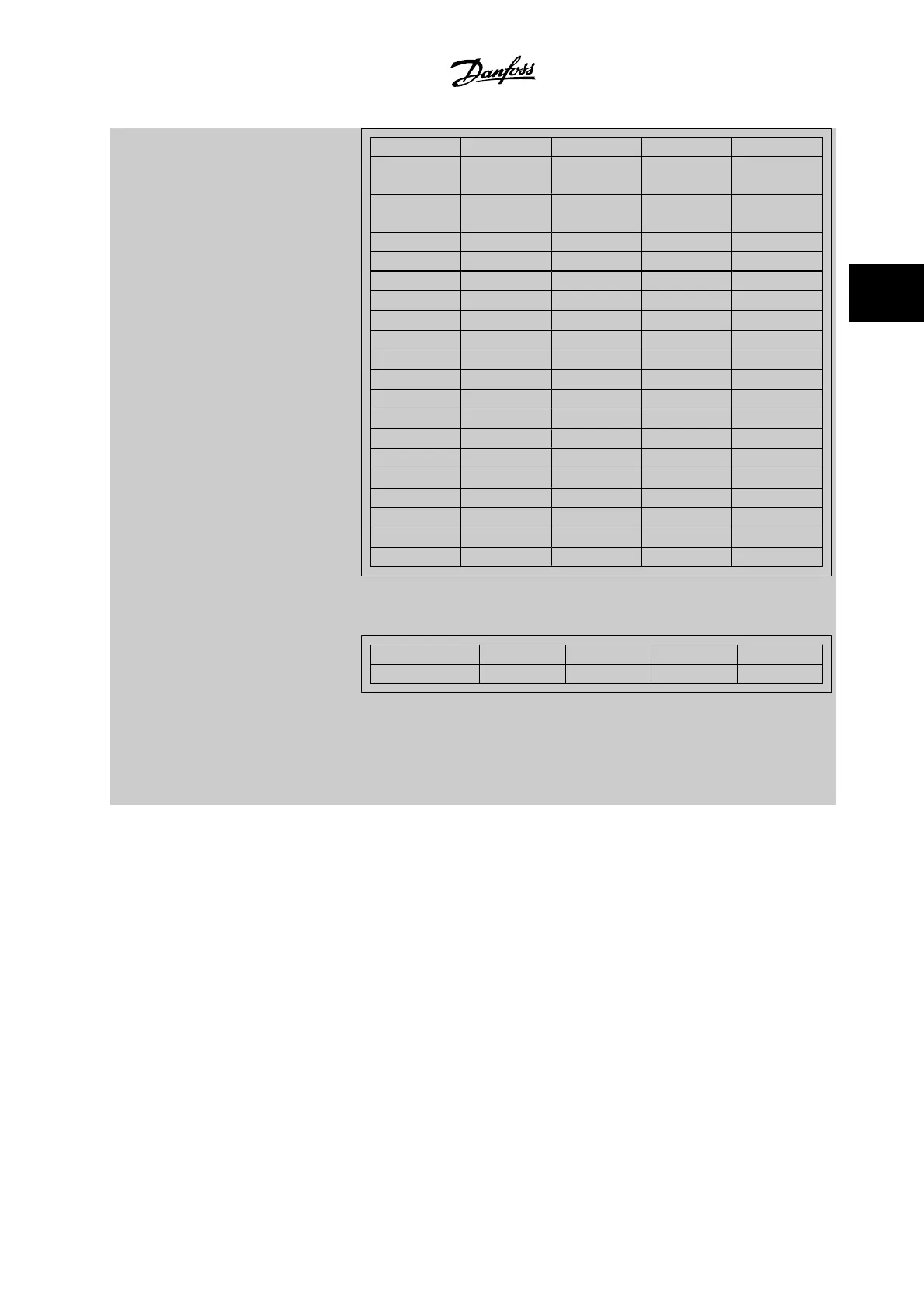
Position 4⇒ Valve Fan bearings Pump bearings Motor bearings
Position 3 ⇒ Pump seals Temperature
transmitter
Flow transmitter Pressure trans-
mitter
Position 2 ⇒ Drive system
health check
Drive cooling fan Filter Fan belt
Position 1⇒ Warranty
0
hex
- - - -
1
hex
- - - +
2
hex
- - + -
3
hex
- - + +
4
hex
- + - -
5
hex
- + - +
6
hex
- + + -
7
hex
- + + +
8
hex
+ - - -
9
hex
+ - - +
A
hex
+ - + -
B
hex
+ - + +
C
hex
+ + - -
D
hex
+ + - +
E
hex
+ + + -
F
hex
+ + + +
Example:
The Preventive Maintenance Word shows 040Ahex.
Position
1 2 3 4
hex value 0 4 0 A
The first digit 0 indicates that no items from the fourth row requires maintenance
The second digit 4 refers to the third row indicating that the drive cooling fan requires maintenance
The third digit 0 indicates that no items from the second row requires maintenance
The fourth digit A refers to the top row indicating that the valve and the pump bearings require
maintenance
VLT
®
HVAC Drive Programming Guide 3 Parameter Description
MG.11.C6.22 - VLT
®
is a registered Danfoss trademark
3-161
3

 Loading...


