There are two methods which can be employed, depending upon whether or not the Speed at System design Working Point is known.
Parameter used
Speed at
Design Point
KNOWN
Speed at
Design Point
UNKNOWN
Cascade Controller
Flow Compensation, 22-80 + + +
Square-Linear Curve Approximation, 22-81 + + -
Work Point Calculation, 22-82 + + -
Speed at No Flow, 22-83/84 + + -
Speed at Design Point, 22-85/86 + - -
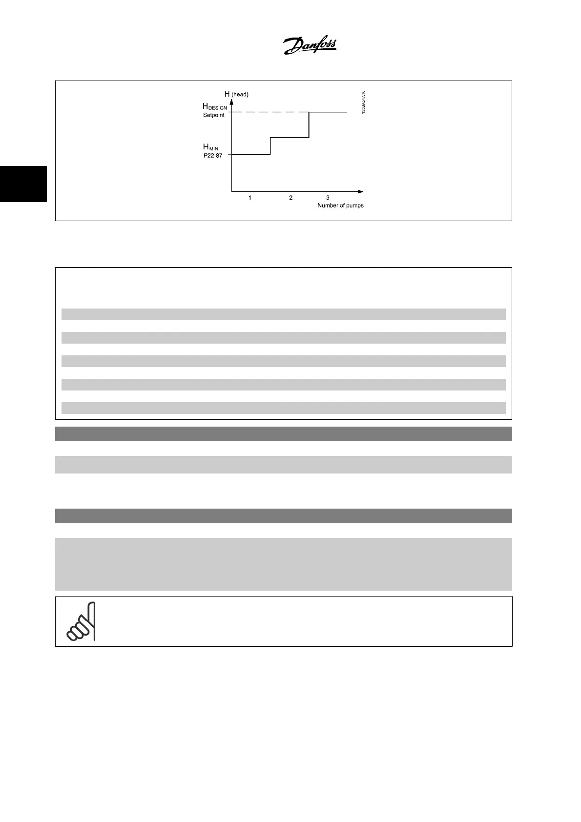
Pressure at No Flow, 22-87 + + +
Pressure at Rated Speed, 22-88 - + -
Flow at Design Point, 22-89 - + -
Flow at Rated Speed, 22-90 - + -
22-80 Flow Compensation
Option: Function:
[0] * Disabled [0]
Disabled
: Setpoint compensation not active.
[1] Enabled [1]
Enabled
: Setpoint compensation is active. Enabling this parameter allows the Flow Compensated
Setpoint operation.
22-81 Square-linear Curve Approximation
Range: Function:
100 %* [0 - 100 %] Example 1:
Adjustment of this parameter allows the shape of the control curve to be adjusted.
0 = Linear
100% = Ideal shape (theoretical).
NOTE!
Please note: Not visible when running in cascade.
3 Parameter Description VLT
®
HVAC Drive Programming Guide
3-208
MG.11.C6.22 - VLT
®
is a registered Danfoss trademark
3

 Loading...


