22-82 Work Point Calculation
Option: Function:
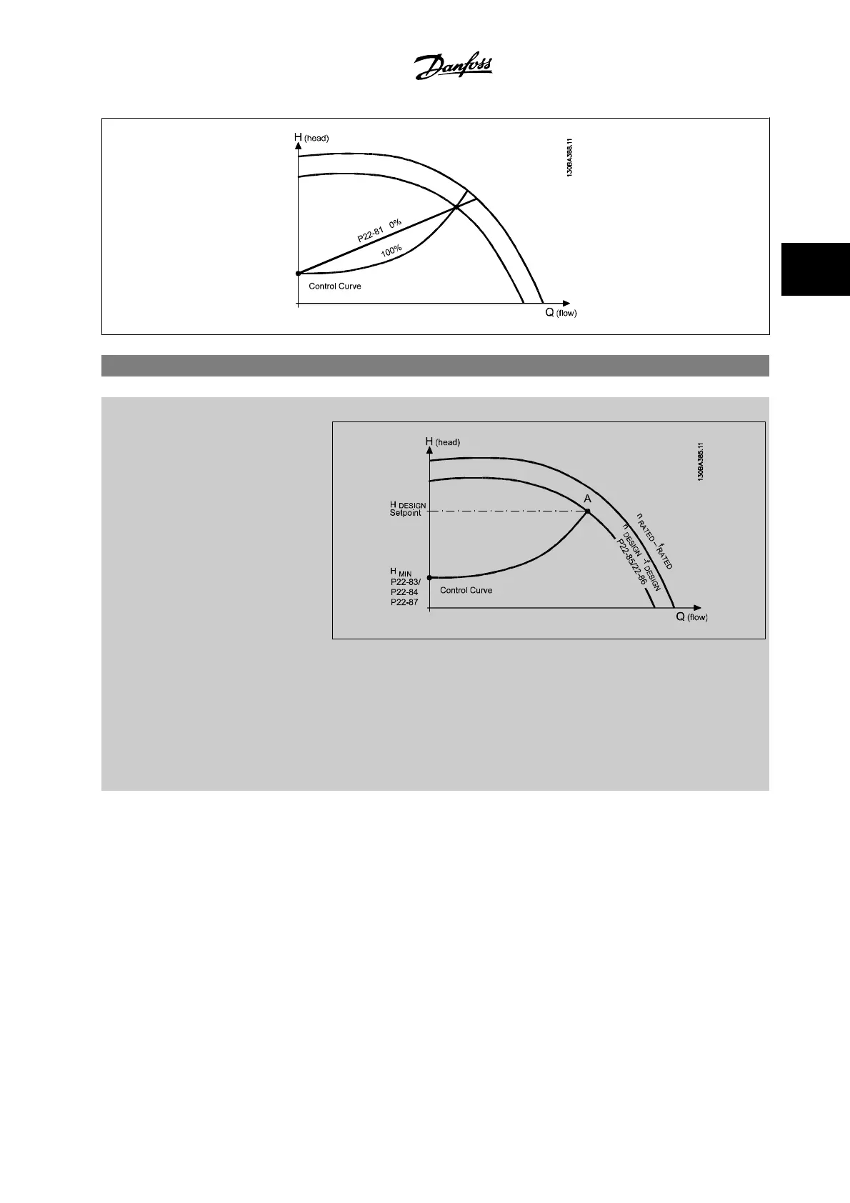
Example 1: Speed at System Design Working Point is known:
From the data sheet showing characteristics for the specific equipment at different speeds, simply
reading across from the H
DESIGN
point and the Q
DESIGN
point allows us to find point A, which is the
system design working point. The pump characteristics at this point should be identified and the
associated speed programmed. Closing the valves and adjusting the speed until H
MIN
has been
achieved allows the speed at the no flow point to be identified.
Adjustment of par.22-81
Square-linear Curve Approximation
then allows the shape of the control
curve to be adjusted infinitely.
VLT
®
HVAC Drive Programming Guide 3 Parameter Description
MG.11.C6.22 - VLT
®
is a registered Danfoss trademark
3-209
3

 Loading...


