Example 2:
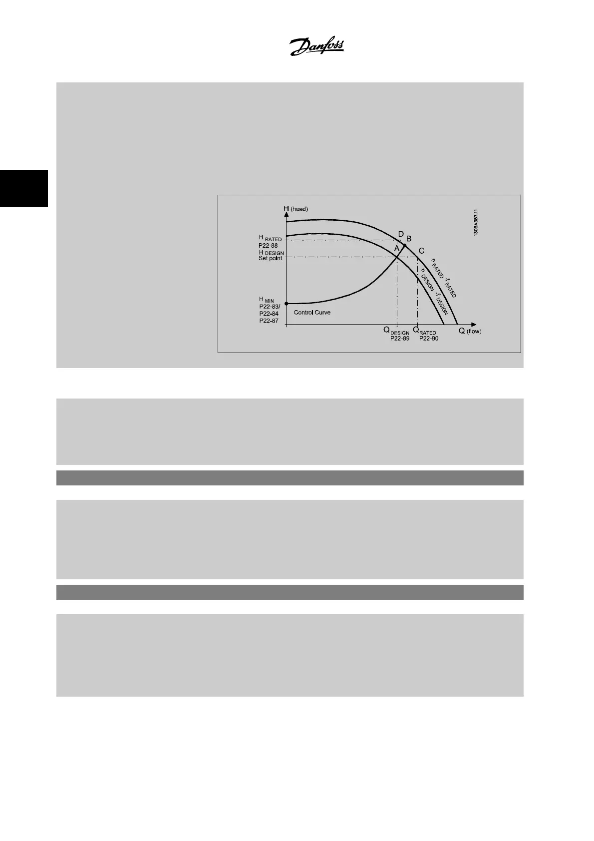
Speed at System Design Working Point is not known: Where the Speed at System Design Working
Point is unknown, another reference point on the control curve needs to be determined by means
of the data sheet. By looking at the curve for the rated speed and plotting the design pressure
(H
DESIGN
, Point C), the flow at that pressure Q
RATED
can be determined. Similarly, by plotting the
design flow (Q
DESIGN
, Point D), the pressure H
D
at that flow can be determined. Knowing these two
points on the pump curve, along with H
MIN
described above, allows the adjustable frequency drive
to calculate the reference point B and thus to plot the control curve that will also include the system
design working point A.
[0] * Disabled
Disabled [0]
: Work Point Calculation not active. To be used if speed at design point is known (see
table above).
[1] Enabled
Enabled [1]
: Work Point Calculation is active. Enabling this parameter allows the calculation of the
unknown System Design Working Point at 50/60 Hz speed, from the input data set in par.
22-83
Speed at No-Flow [RPM]
par.22-84
Speed at No-Flow [Hz]
, par.22-87
Pressure at No-Flow
Speed
, par.22-88
Pressure at Rated Speed
, par.22-89
Flow at Design Point
and par.22-90
Flow at
Rated Speed
.
22-83 Speed at No-Flow [RPM]
Range: Function:
300. RPM* [0 - par. 22-85 RPM] Resolution 1 RPM.
The speed of the motor at which the flow is zero and the minimum pressure H
MIN
is achieved should
be entered here in RPM. Alternatively, the speed in Hz can be entered in par.22-84
Speed at No-
Flow [Hz]
. If it has been decided to use RPM in par.0-02
Motor Speed Unit
, then par.22-85
Speed
at Design Point [RPM]
should also be used. Closing the valves and reducing the speed until minimum
pressure H
MIN
is achieved will determine this value.
22-84 Speed at No-Flow [Hz]
Range: Function:
50.0 Hz* [0.0 - par. 22-86 Hz] Resolution 0.033 Hz.
The speed of the motor at which flow has effectively stopped and minimum pressure H
MIN
is achieved
should be entered here in Hz. Alternatively, the speed in RPM can be entered in par.22-83
Speed
at No-Flow [RPM]
. If it has been decided to use Hz in par.0-02
Motor Speed Unit
, then par.
22-86
Speed at Design Point [Hz]
should also be used. Closing the valves and reducing the speed
until minimum pressure H
MIN
is achieved will determine this value.
3 Parameter Description VLT
®
HVAC Drive Programming Guide
3-210
MG.11.C6.22 - VLT
®
is a registered Danfoss trademark
3

 Loading...


