system while the SBW timers are running. The value can be optimized with increased familiarity
with the system. See par.25-25
OBW Time
.
To avoid unintended staging during the commissioning phase and fine tuning of the controller,
initially leave the OBW at the factory setting of 100% (Off). When the fine tuning is completed, the
OBW should be set to the desired value. An initial value of 10% is suggested.
25-22 Fixed Speed Bandwidth
Range: Function:
par. 25-20
%*
[par. 25-20 - par. 25-21 %] When the cascade control system is running normally and the adjustable frequency drive issues a
trip alarm, it is important to maintain the system head. The cascade controller does this by con-
tinuing to stage/de-stage the fixed speed pump on and off. Due to the fact that keeping the head
at the setpoint would require frequent staging and de-staging when only a fixed speed pump is
running, a wider Fixed Speed Bandwidth (FSBW) is used instead of SBW. It is possible to stop the
fixed speed pumps, in case of an alarm situation, by pressing the LCP OFF or HAND ON keys or if
the signal programmed for Start on digital input goes low.
If the issued alarm is a trip-lock alarm, the cascade controller must stop the system immediately by
cutting out all the fixed speed pumps. This is basically the same as Emergency Stop (Coast/Coast
inverse Command) for the cascade controller.
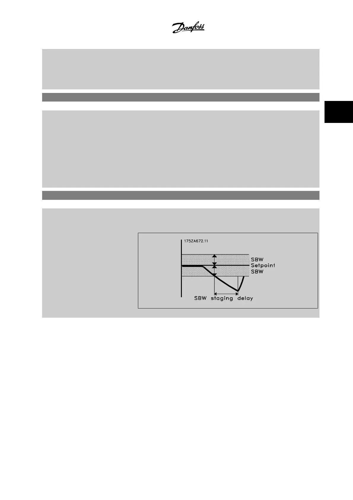
25-23 SBW Staging Delay
Range: Function:
15 s* [0 - 3000 s] Immediate staging of a fixed speed pump is not desirable when a momentary pressure drop in the
system exceeds the staging bandwidth (SBW). Staging is delayed by the length of time programmed.
If the pressure increases to within the SBW before the timer has elapsed, the timer is reset.
VLT
®
HVAC Drive Programming Guide 3 Parameter Description
MG.11.C6.22 - VLT
®
is a registered Danfoss trademark
3-239
3

 Loading...


