[57] DigiPot Clear Uses the input to CLEAR the Digital Potentiometer reference described in parameter group 3-9*
[60] Counter A (up) (Terminal 29 or 33 only) Input for increment counting in the SLC counter.
[61] Counter A (down) (Terminal 29 or 33 only) Input for decrement counting in the SLC counter.
[62] Reset Counter A Input for reset of counter A.
[63] Counter B (up) (Terminal 29 and 33 only) Input for increment counting in the SLC counter.
[64] Counter B (down) (Terminal 29 and 33 only) Input for decrement counting in the SLC counter.
[65] Reset Counter B Input for reset of counter B.
[66] Sleep Mode Forces the adjustable frequency drive into sleep mode (see par. 22-4*). Reacts on the rising edge
of signal applied!
[78] Reset Preventive Maintenance Word Resets all data in par.16-96
Maintenance Word
to 0.
The below setting options are all related to the cascade controller. Wiring diagrams and settings for parameter, see group 25-** for more details.
[120] Lead Pump Start Starts/stops the lead pump (controlled by the adjustable frequency drive). A start requires that also
a System Start signal has been applied, e.g., to one of the digital inputs set for
Start
[8]!
[121] Lead Pump Alternation Forces alternation of the lead pump in a cascade controller. par.25-50
Lead Pump Alternation
, must
be set to either
At Command
[2] or
At Staging or At Command
[3]. par.25-51
Alternation Event
,
can be set to any of the four options.
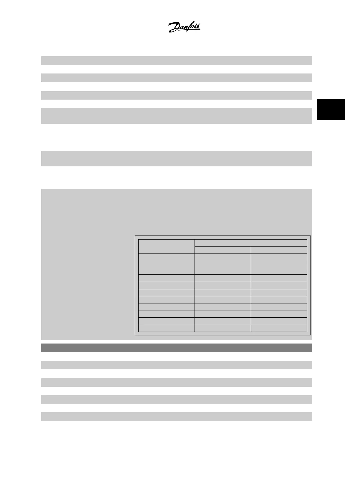
[130 - 138] Pump1 Interlock - Pump9 Interlock For the above 9 setting options, par. 25-10 must be set to
On
[1]. The function will also depend on
the setting in par.25-05
Fixed Lead Pump
. If set to
No
[0], then Pump1 refers to the pump controlled
by relay RELAY1, etc. If set to
Yes
[1], Pump1 refers to the pump controlled by the adjustable
frequency drive only (without any of the built-in relays involved) and Pump2 to the pump controlled
by the relay RELAY1. Variable speed pump (lead) cannot be interlocked.
See below table:
Setting in Par. 5-1*
Setting in par.25-06
Number Of Pumps
[0] No [1] Yes
[130] Pump1 Interlock Controlled by RELAY1
(only if not lead pump)
Adjustable frequency drive
controlled
(cannot be interlocked)
[131] Pump2 Interlock Controlled by RELAY2 Controlled by RELAY1
[132] Pump3 Interlock Controlled by RELAY3 Controlled by RELAY2
[133] Pump4 Interlock Controlled by RELAY4 Controlled by RELAY3
[134] Pump5 Interlock Controlled by RELAY5 Controlled by RELAY4
[135] Pump6 Interlock Controlled by RELAY6 Controlled by RELAY5
[136] Pump7 Interlock Controlled by RELAY7 Controlled by RELAY6
[137] Pump8 Interlock Controlled by RELAY8 Controlled by RELAY7
[138] Pump9 Interlock Controlled by RELAY9 Controlled by RELAY8
5-10 Terminal 18 Digital Input
Option: Function:
[0] No operation
[1] Reset
[2] Coast inverse
[3] Coast and Reset Inv
[5] DC brake inverse
[6] Stop inverse
[7] External interlock
VLT
®
HVAC Drive Programming Guide 3 Parameter Description
MG.11.C6.22 - VLT
®
is a registered Danfoss trademark
3-51
3

 Loading...


