20-20 Feedback Function
Value:
Sum [0]
Difference [1]
Average [2]
Minimum [3]
Maximum [4]
Multi setpoint min [5]
Multi setpoint max [6]
Function:
This parameter determines how the three
possible feedbacks will be used to control the
output frequency of the frequency converter.
NB!
Any unused feedback must be
set to “No function” in its Feed-
back Source parameter: 20-00,
20-03 or 20-06.
The feedback resulting from the function se-
lected in par. 20-20 will be used by the PID
Controller to control the output frequency of
the frequency converter. This feedback can
also be shown on the frequency converter’s
display, be used to control a frequency con-
verter's analog output, and be transmitted
over various serial communication protocols.
The frequency converter can be configured to
handle multi zone applications. Two different
multi zone applications are supported:
• Multi zone, single setpoint
• Multi zone, multi setpoint
The difference between the two is illustrated
by the following examples:
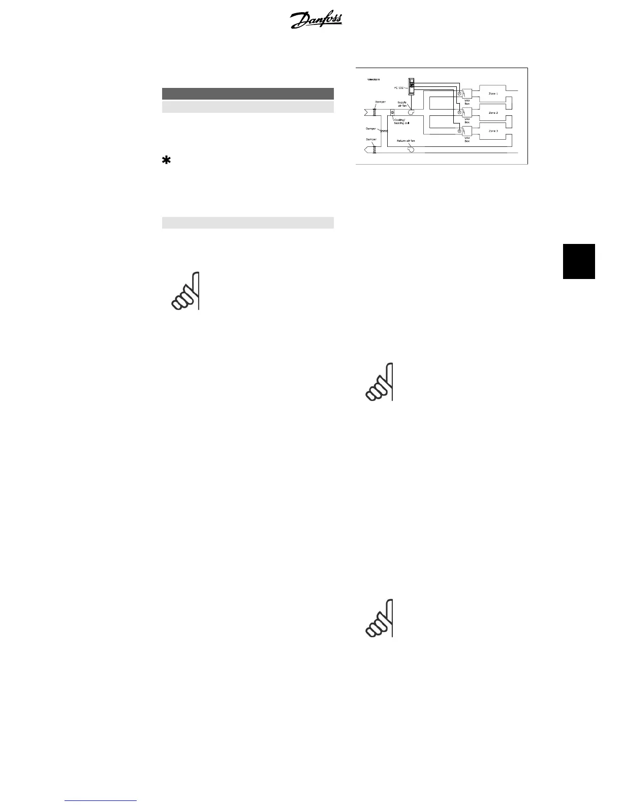
Example 1 – Multi zone, single setpoint
In an office building, a VAV (variable air vol-
ume) HVAC system must ensure a minimum
pressure at selected VAV boxes. Due to the
varying pressure losses in each duct, the pres-
sure at each VAV box cannot be assumed to
be the same. The minimum pressure required
is the same for all VAV boxes. This control
method can be set up by setting
Feedback
Function
, par. 20-20 to option [3], Minimum,
and entering the desired pressure in par.
20-21. The PID Controller will increase the
speed of the fan if any one feedback is below
the setpoint and decrease the speed of the fan
if all feedbacks are above the setpoint.
Example 2 – Multi zone, multi setpoint
The previous example can be used to illustrate
the use of multi zone, multi setpoint control.
If the zones require different pressures for
each VAV box, each setpoint may be specified
in par. 20-21, 20-22 and 20-23. By selecting
Multi setpoint minimum
, [5], in par. 20-20,
Feedback Function, the PID Controller will in-
crease the speed of the fan if any one of the
feedbacks is below its setpoint and decrease
the speed of the fan if all feedbacks are above
their individual setpoints.
Sum
[0] sets up the PID Controller to use the
sum of Feedback 1, Feedback 2 and Feedback
3 as the feedback.
NB!
Any unused feedbacks must be
set to
No Function
in par. 20-00,
20-03, or 20-06.
The sum of Setpoint 1 and any other referen-
ces that are enabled (see par. group 3-1*) will
be used as the PID Controller’s setpoint ref-
erence.
Difference
[1] sets up the PID Controller to
use the difference between Feedback 1 and
Feedback 2 as the feedback. Feedback 3 will
not be used with this selection. Only setpoint
1 will be used. The sum of Setpoint 1 and any
other references that are enabled (see par.
group 3-1*) will be used as the PID
Controller’s setpoint reference.
Average
[2] sets up the PID Controller to use
the average of Feedback 1, Feedback 2 and
Feedback 3 as the feedback.
NB!
Any unused feedbacks must be
set to
No Function
in par. 20-00,
20-03, or 20-06. The sum of
Setpoint 1 and any other refer-
ences that are enabled (see par.
group 3-1*) will be used as the
PID Controller’s setpoint refer-
ence.
VLT
®
HVAC Drive Operating Instructions 6. How to programme the frequency converter
MG.11.A4.02 - 09.10.06. VLT
®
is a registered Danfoss trademark
79
6