EasyManuals Logo

Danfoss VLT HVAC User Manual

Danfoss VLT HVAC
145 pages
To Next Page IconTo Next Page
To Previous Page IconTo Previous Page
Page #33 background imageLoading...
Page #33 background image
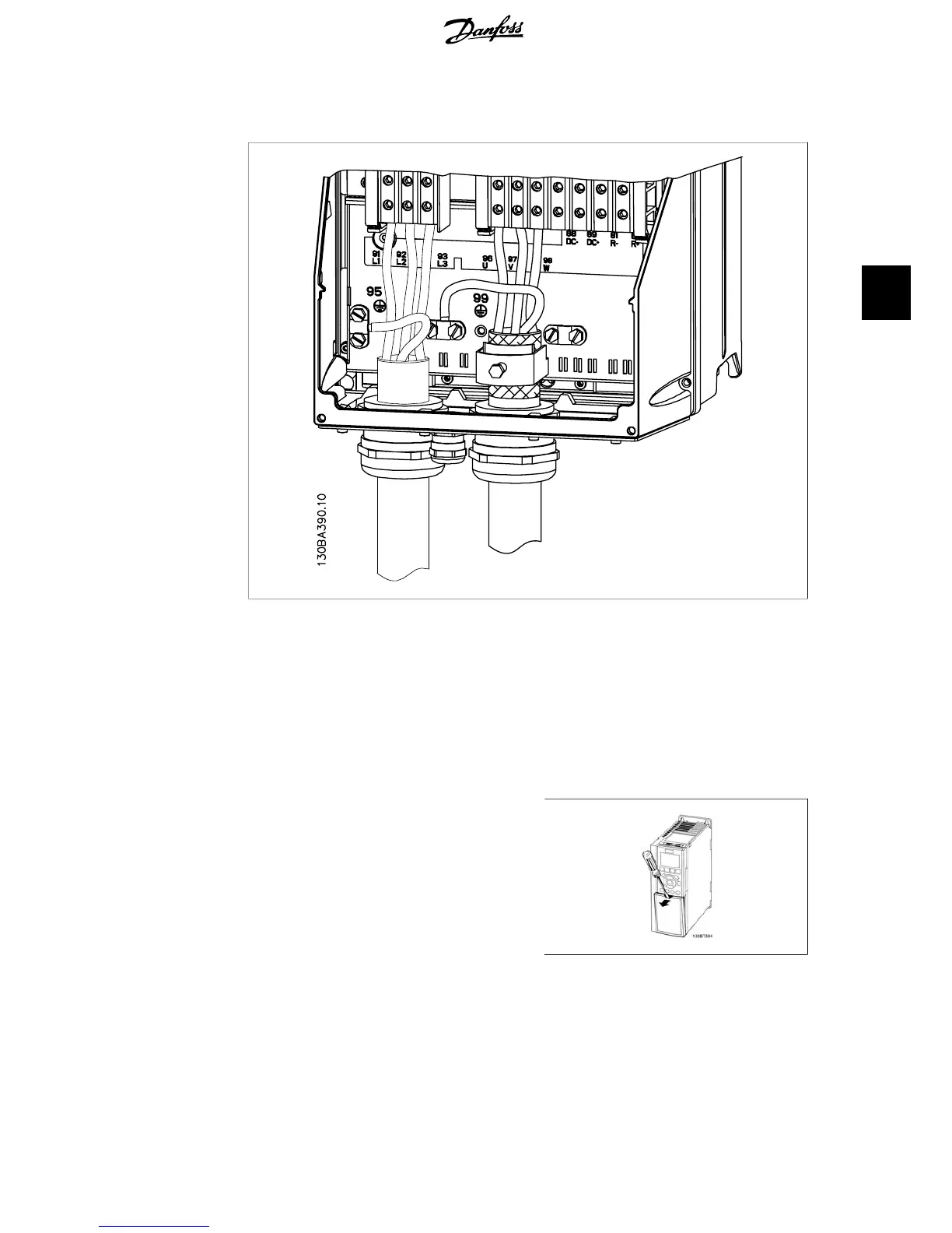
4.1.14. Motor connection for C1 and C2
Illustration 4.15: First terminate the motor earth, then Place motor U, V and W wires in terminal and tighten.
Please ensure that the outer insulation of the motor cable is removed under the EMC clamp.
4.1.15. Wiring Example and Testing
The following section describes how to terminate control wires and how to access them. For an
explanation of the function, programming and wiring of the control terminals, please see chapter,
How to programme the frequency converter.
4.1.16. Access to Control Terminals
All terminals to the control cables are located
underneath the terminal cover on the front of
the frequency converter. Remove the terminal
cover with a screwdriver.
Illustration 4.16: A2 and A3 enclosures
VLT
®
HVAC Drive Operating Instructions 4. Electrical installation
MG.11.A4.02 - 09.10.06. VLT
®
is a registered Danfoss trademark
33
4

Other manuals for Danfoss VLT HVAC

Questions and Answers:

Question and Answer IconNeed help?

Do you have a question about the Danfoss VLT HVAC and is the answer not in the manual?

Danfoss VLT HVAC Specifications

General IconGeneral
Enclosure RatingIP20, IP21, IP54, IP55, IP66
Storage Temperature Range-25°C to +70°C
Output Voltage Range0-100% of supply voltage
Communication ProtocolsModbus RTU, BACnet, Ethernet/IP, Profibus DP
Ambient Temperature Range-10°C to +50°C (without derating)
Relative Humidity5% to 95% non-condensing
AltitudeUp to 1000 m without derating
Cooling MethodAir cooled
ApplicationHVAC systems, Pumps, Fans, Compressors
Voltage Range200-240 V, 380-500 V, 525-600 V
Frequency Range0 Hz to 590 Hz

Related product manuals