EasyManuals Logo

Danfoss VLT HVAC User Manual

Danfoss VLT HVAC
145 pages
To Next Page IconTo Next Page
To Previous Page IconTo Previous Page
Page #34 background imageLoading...
Page #34 background image
Remove front-cover to access control termi-
nals. When replacing the front-cover, please
ensure proper fastening by applying a torque
of 2 Nm.
Illustration 4.17: A5, B1,B2, C1 and C2 enclosures
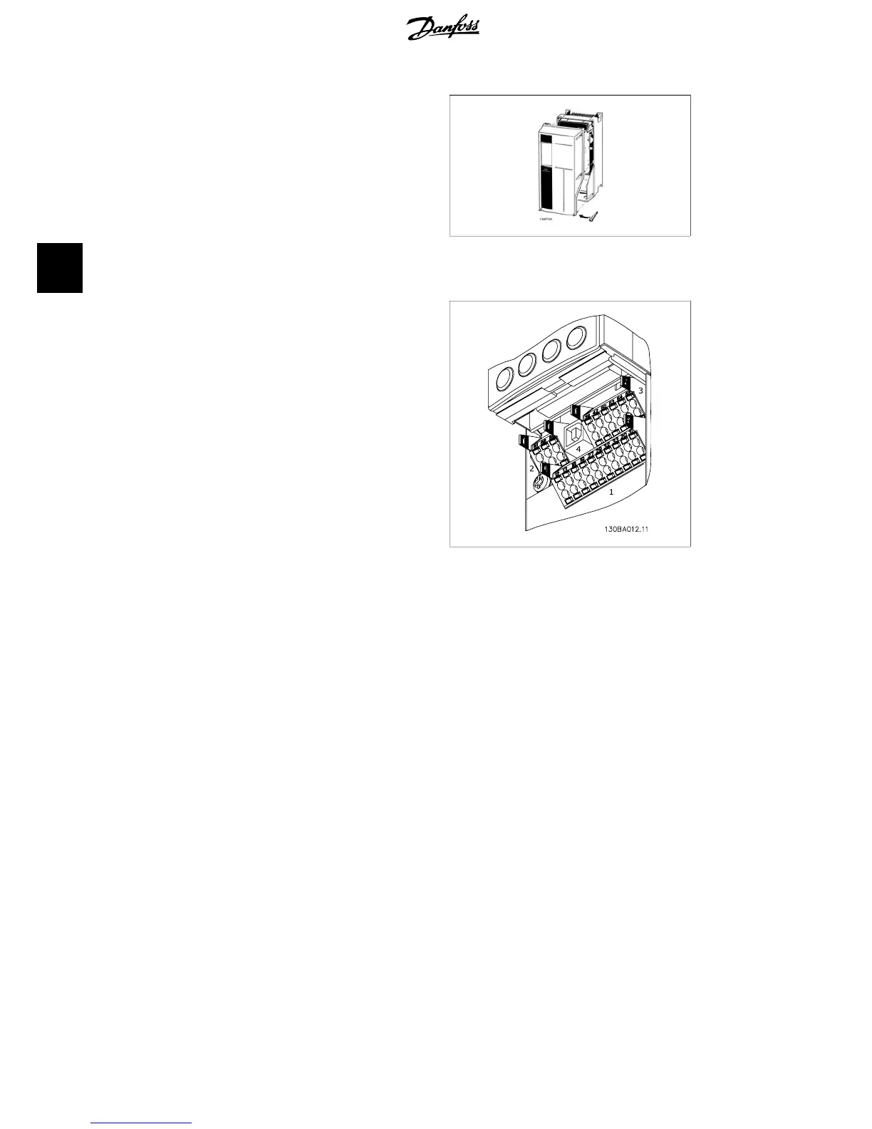
4.1.17. Control Terminals
Drawing reference numbers:
1. 10 pole plug digital I/O.
2. 3 pole plug RS-485 Bus.
3. 6 pole analog I/O.
4. USB connection.
Illustration 4.18: Control terminals (all enclosures)
4. Electrical installation VLT
®
HVAC Drive Operating Instructions
34
MG.11.A4.02 - 09.10.06. VLT
®
is a registered Danfoss trademark
4

Other manuals for Danfoss VLT HVAC

Questions and Answers:

Question and Answer IconNeed help?

Do you have a question about the Danfoss VLT HVAC and is the answer not in the manual?

Danfoss VLT HVAC Specifications

General IconGeneral
Enclosure RatingIP20, IP21, IP54, IP55, IP66
Storage Temperature Range-25°C to +70°C
Output Voltage Range0-100% of supply voltage
Communication ProtocolsModbus RTU, BACnet, Ethernet/IP, Profibus DP
Ambient Temperature Range-10°C to +50°C (without derating)
Relative Humidity5% to 95% non-condensing
AltitudeUp to 1000 m without derating
Cooling MethodAir cooled
ApplicationHVAC systems, Pumps, Fans, Compressors
Voltage Range200-240 V, 380-500 V, 525-600 V
Frequency Range0 Hz to 590 Hz

Related product manuals