4. Electrical installation
4.1. How to connect
4.1.1. Cables General
NB!
Cables General
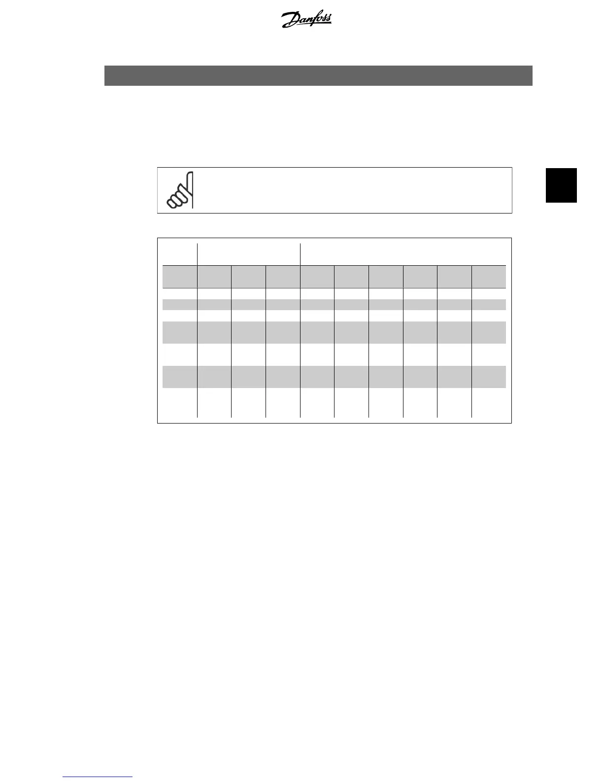
Always comply with national and local regulations on cable cross-sections.
Details of terminal tightening torques.
Power (kW) Torque (Nm)
Enclo-
sure
200-24
0 V
380-48
0 V
525-60
0 V
Line Motor
DC con-
nection
Brake Earth Relay
A2 1.1 - 3.0 1.1 - 4.0 1.1 - 4.0 1.8 1.8 1.8 1.8 3 0.6
A3 3.7 5.5 - 7.5 5.5 - 7.5 1.8 1.8 1.8 1.8 3 0.6
A5 1.1 - 3.7 1.1 - 7.5 1.1 - 7.5 1.8 1.8 1.8 1.8 3 0.6
B1 5.5 - 11
11 -
18.5
- 1.8 1.8 1.5 1.5 3 0.6
B2
-
15
22
30
-
-
2.5
4.5
2.5
4.5
3.7
3.7
3.7
3.7
3
3
0.6
0.6
C1
18.5 -
30
37 - 55 - 10 10 10 10 3 0.6
C2
37
45
75
90
-
-
14
24
14
24
14
14
14
14
3
3
0.6
0.6
Table 4.1: Tightening of terminals.
4.1.2. Fuses
Branch circuit protection
In order to protect the installation against electrical and fire hazard, all branch circuits in an in-
stallation, switch gear, machines etc., must be shortcircuit and overcurrent protected according
to the national/international regulations.
Short circuit protection
The frequency converter must be protected against short-circuit to avoid electrical or fire hazard.
Danfoss recommends using the fuses mentioned in tables 4.3 and 4.4 to protect service personnel
or other equipment in case of an internal failure in the unit. The frequency converter provides full
short circuit protection in case of a short-circuit on the motor output.
Over-current protection
Provide overload protection to avoid fire hazard due to overheating of the cables in the installation.
Over current protection must always be carried out according to national regulations. The fre-
quency converter is equipped with an internal over current protection that can be used for
upstream overload protection (UL-applications excluded). See VLT
®
HVAC Drive Programming
Guide, par. 4-18. Fuses must be designed for protection in a circuit capable of supplying a maxi-
mum of 100,000 A
rms
(symmetrical), 500 V/600 V maximum.
VLT
®
HVAC Drive Operating Instructions 4. Electrical installation
MG.11.A4.02 - 09.10.06. VLT
®
is a registered Danfoss trademark
21
4
 Loading...


