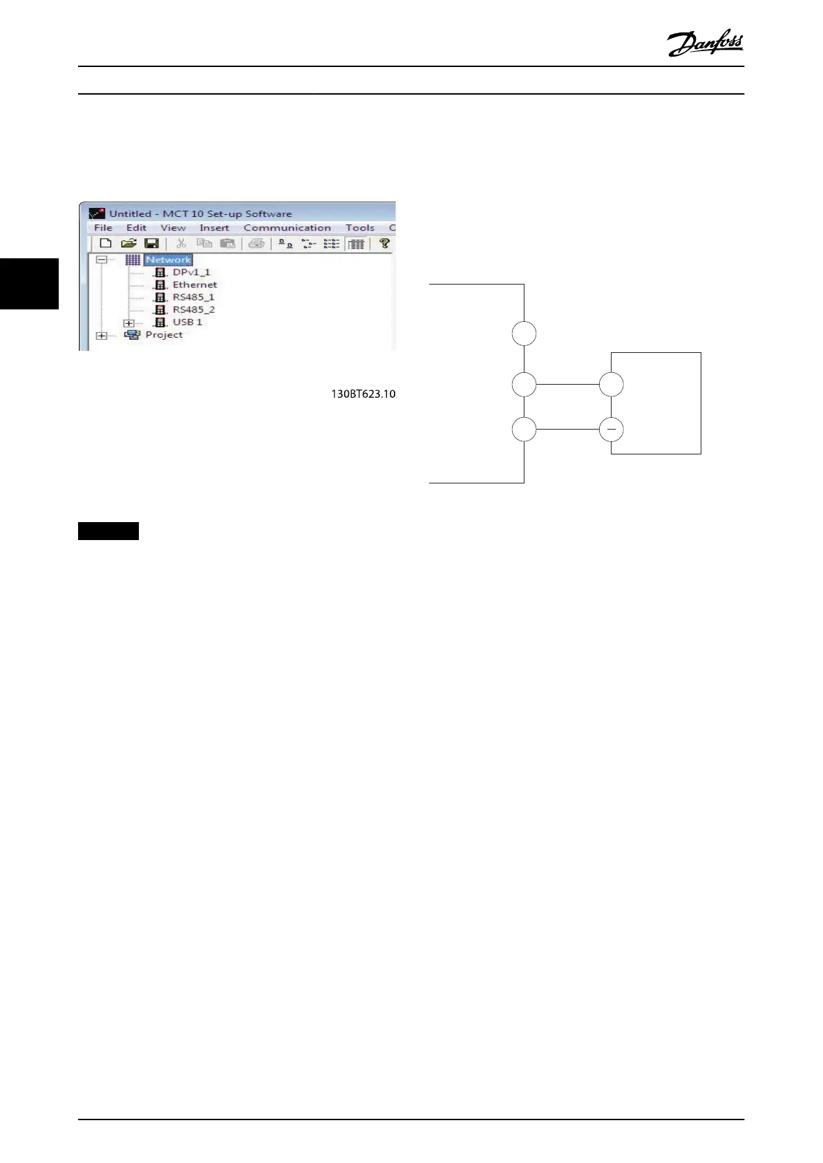
4.8.5 USB Data Communication
Illustration 4.13 Network Bus List
When the USB cable is disconnected, the frequency
converter connected via the USB port is removed from the
Network bus list.
NOTICE
A USB bus has no address-setting capacity and no bus
name to congure. If connecting more than 1 frequency
converter through USB, the bus name is auto-
incremented in the MCT 10 Set-up Software Network bus
list.
Connecting more than 1 frequency converter through a
USB cable often causes computers installed with
Windows XP to throw an exception and crash. Therefore
it is advised only to connect 1 frequency converter via
USB to the PC.
4.8.6 RS485 Serial Communication
Connect RS485 serial communication wiring to terminals
(+)68 and (-)69.
•
Shielded serial communication cable is
recommended.
•
See chapter 4.3 Grounding for proper grounding.
Illustration 4.14 Serial Communication Wiring Diagram
For basic serial communication set-up, select the following:
1. Protocol type in parameter 8-30 Protocol.
2. Frequency converter address in
parameter 8-31 Address.
3. Baud rate in parameter 8-32 Baud Rate.
Two communication protocols are internal to the
frequency converter. Follow motor manufacturer wiring
requirements.
•
Danfoss FC
•
Modbus RTU
Functions can be programmed remotely using the protocol
software and RS485 connection, or in parameter group 8-**
Communications and Options.
Selecting a specic communication protocol changes
various default parameter settings to match the speci-
cations of the protocol and makes extra protocol-specic
parameters available.
Electrical Installation
VLT
®
Midi Drive FC 280
22 Danfoss A/S © 10/2017 All rights reserved. MG07A402
44

 Loading...


