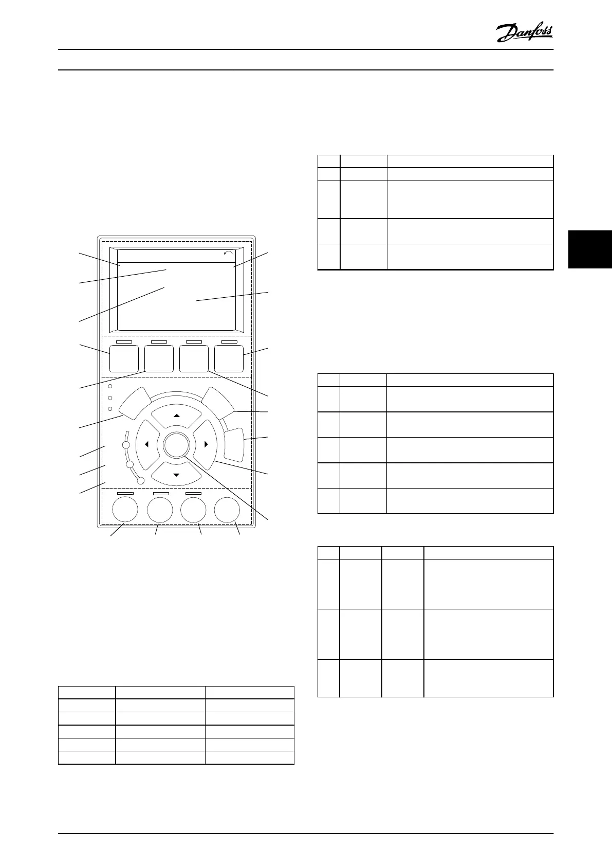
5.3.5 Graphic Local Control Panel (GLCP)
The GLCP is divided into 4 functional groups (see
Illustration 5.8).
A. Display area.
B. Display menu keys.
C. Navigation keys and indicator lights (LEDs).
D. Operation keys and reset.
130BD598.10
Auto
On
Reset
Hand
On
O
Status
Quick
Menu
Main
Menu
Alarm
Log
Back
Cancel
Info
OK
Status
1(1)
36.4 kW
Auto Remote Ramping
0.000
On
Alarm
Warn.
A
7.83 A
799 RPM
B
C
D
53.2 %
1
2
3
4
5
6
7
8
9
10
11
12
13
14
15
16
17
18 19 20 21
Illustration 5.8 Graphic Local Control Panel (GLCP)
A. Display area
The display area is activated when the frequency converter
receives power from the mains voltage, a DC bus terminal,
or a 24 V DC external supply.
The information shown on the LCP can be customized for
user applications. Select options in the Quick Menu Q3-13
Display Settings.
Display Parameter number Default setting
1 0-20 [1602] Reference [%]
2 0-21 [1614] Motor Current
3 0-22 [1610] Power [kW]
4 0-23 [1613] Frequency
5 0-24 [1502] kWh Counter
Table 5.8 Legend to Illustration 5.8, Display Area
B. Display menu keys
Menu keys are used for menu access for parameter set-up,
toggling through status display modes during normal
operation, and viewing fault log data.
Key Function
6 Status Shows operational information.
7
Quick
Menu
Allows access to programming parameters
for initial set-up instructions and many
detailed application instructions.
8 Main Menu
Allows access to all programming
parameters.
9 Alarm Log
Shows a list of current warnings, the last 10
alarms, and the maintenance log.
Table 5.9 Legend to Illustration 5.8, Display Menu Keys
C. Navigation keys and indicator lights (LEDs)
Navigation keys are used for programming functions and
moving the display cursor. The navigation keys also
provide speed control in local operation. There are also 3
frequency converter status indicator lights in this area.
Key Function
10 Back
Reverts to the previous step or list in the
menu structure.
11 Cancel
Cancels the last change or command as long
as the display mode has not changed.
12 Info
Press for a denition of the function being
shown.
13
Navigation
keys
To move between items in the menu, use the
4 navigation keys.
14 OK
Press to access parameter groups or to
enable a selection.
Table 5.10 Legend to Illustration 5.8, Navigation Keys
Indicator Light Function
15 On Green
ON turns on when the frequency
converter receives power from the
mains voltage, a DC bus terminal,
or a 24 V external supply.
16 Warn Yellow
When warning conditions are met,
the yellow WARN LED turns on,
and text appears in the display
area identifying the problem.
17 Alarm Red
A fault condition causes the red
alarm LED to ash, and an alarm
text is shown.
Table 5.11 Legend to Illustration 5.8, Indicator Lights (LEDs)
Commissioning Operating Guide
MG07A402 Danfoss A/S © 10/2017 All rights reserved. 31
5 5

 Loading...


