Table 7.6 indicates the bit functions and the corresponding bit values which are active for this example.
Bit Bit value=0 Bit value=1 Bit value
00 Control not ready Control ready 1
7
01 Drive not ready Drive ready 1
02 Coasting Enable 1
03 No error Trip 0
04 No error Error (no trip) 0
0
05 Reserved – 0
06 No error Trip lock 0
07 No warning Warning 0
08 Speed reference Speed = reference 1
F
09 Local operation Bus control 1
10 Outside frequency range Within frequency range 1
11 No operation In operation 1
12 Drive OK Stopped, auto start 0
0
13 Voltage OK Voltage exceeded 0
14 Torque OK Torque exceeded 0
15 Timers OK Timers exceeded 0
Function active
Function inactive
Table 7.6 Active Bit Functions for Status Word Telegram using PPO Type
7.4
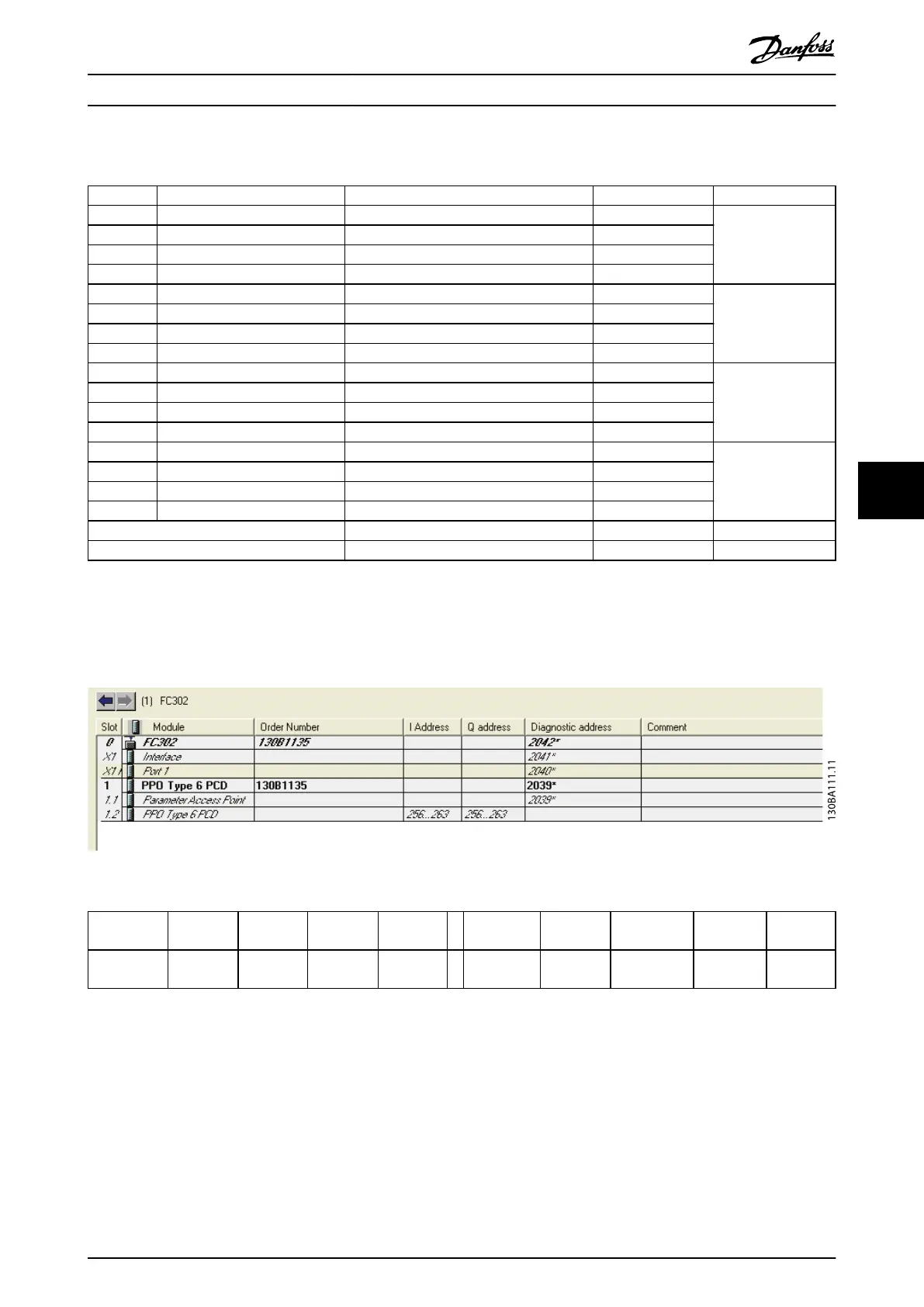
Example 4: PLC Programming
In this example, PPO type 6 is placed in the input/output address, see Illustration 7.2 and Table 7.7.
Illustration 7.2 FC 302 and PPO Type 6 PCD
Input
address
256–257 258–259 260–261 262–263 Output
address
256–257 258–259 260–261 262–263
Set-up Status word MAV Motor
torque
Digital
input
Set-up Control
word
Reference Not used Not used
Table 7.7 Input/Output Address Set-up
Application Examples Programming Guide
MG37G202 Danfoss A/S © 01/2016 All rights reserved. 51
7 7