24
INSTALLATION & SERVICE MANUAL FOR PROFESSIONALS
Product description: Electronic control
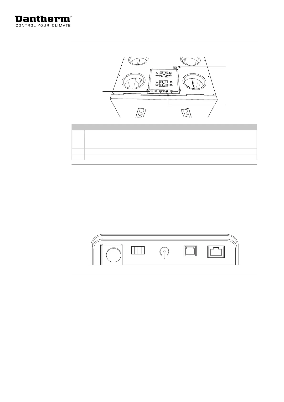
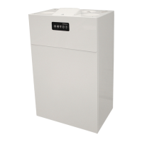
This illustration shows the main PCB and the control panel on the RCV 320.
1
3
2
Fig. 9
Loc. Part
1 USB connection for:
• Use of PC Tool for calibration purposes, software update, change of settings, etc.
• Readout of error list
2 Power and external connections
3 Main PCB (inside the housing) and control panel.
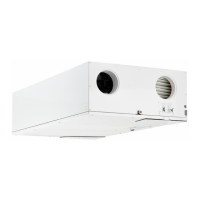
This drawing shows the external connections of the main PCB. Further explanations of how
to use the external connections can be found in the section “External connections” on page
39. See also the wiring diagram on page 52, when connecting to the dierent ports.
Available ports:
• Dig in: External digital input, to select specic operations.
• Antenna: Wireless connection point for product-specic remote control - HRC3
• Modbus: Modbus RTU connection is for internal communication between unit and Dan-
therm accessories (HAC2 + HCP 11 + FPC) only.
• Ethernet: LAN connection
230V
DIG IN ANTENNA
MODBUS
ETHERNET
Fig. 10
Illustration of
unit's control area
External
connections
(Main PCB)