CONNECTIONS
2
2 CONNECTIONS
2.1 CRADLE
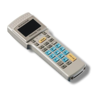
To make the F734-E series terminal operative, it is necessary to
insert it into the Formula 951 Transceiver Charger cradle or into the
Formula 950/4 Multi Transceiver Charger which has been
previously connected to the power supply and to a host computer
with an available RS232, RS485 or Eavesdrop line.
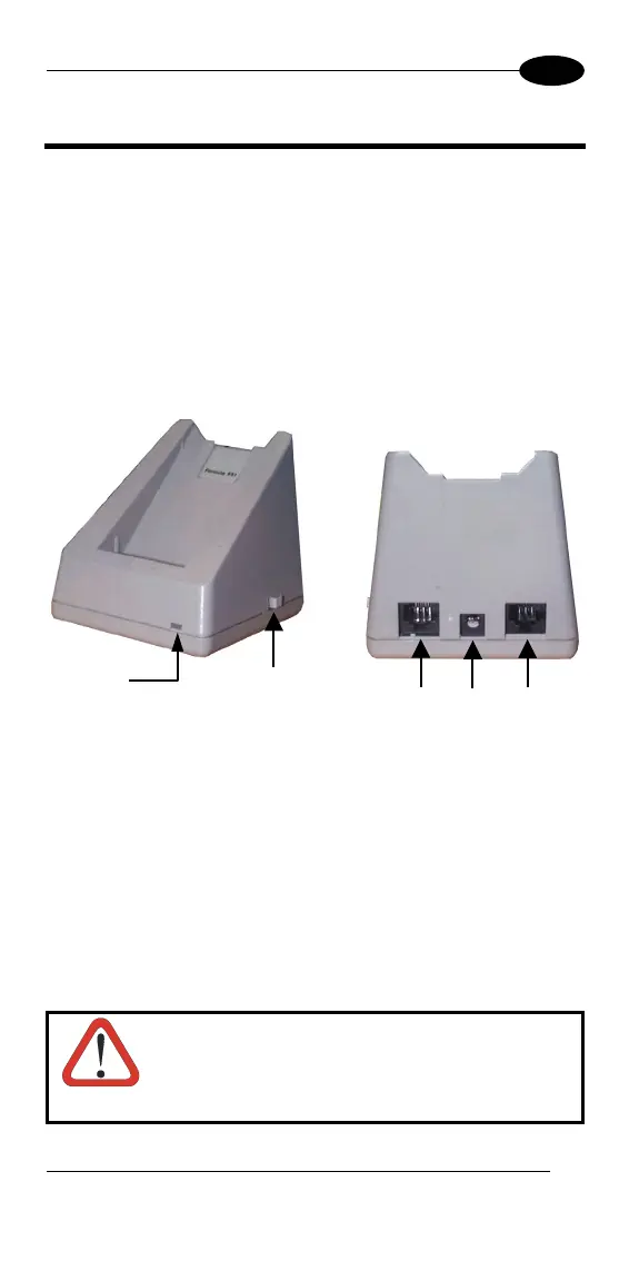
The following figure describes the F951 cradle:
B
A
C ED
Figure 6 - F951 Cradle Overview
Key:
A) Red/Green LED:
Green = terminal not inserted or charge level being maintained
Red = charge in progress
B) Cradle on/off switch
C) RJ connector for RS485 and Eavesdrop connection
D) Power jack (9 V)
E) RJ connector for RS232 and RS485 host connection
CAUTION
The use of cradles other than those expressly
specified may damage the terminal.
7