Installation Manual Rhino™ 10
4
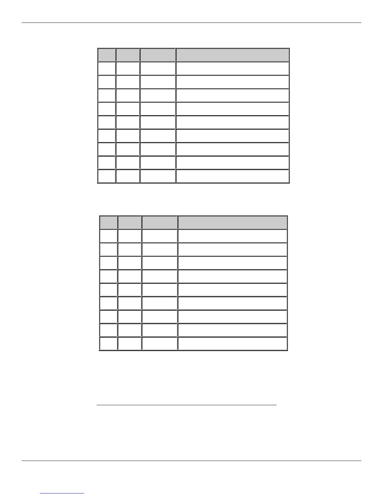
Table 1 – COM1 Pin-Out Description
Pin Name Dir Description
1 CD IN Carrier Detect
2 RXD IN Receive Data
3 TXD OUT Transmit Data
4 DTR OUT Data Terminal Ready
5 GND ------ System Ground
6 DSR IN Data Set Ready
7 RTS OUT Request to Send
8 CTS IN Clear to Send
9 SPWR OUT Power (None, +5V, +12V @ 1A max)
Table 2 – COM2 Pin-out Description
Pin Name Dir Description
1 CD Not connected
2 RXD IN Receive Data
3 TXD OUT Transmit Data
4 DTR OUT Data Terminal Ready (always true)
5 GND ------ System Ground
6 DSR Not connected
7 RTS OUT Request to Send
8 CTS IN Clear to Send
9 SPWR OUT Power (None, +5V, +12V @ 1A max)
Ethernet (optional)
When active, the Ethernet connector allows the Rhino™ 10 to communicate with 10BaseT/100BaseT full duplex stan-
dard Ethernet interfaces. This feature is available on the enten
ded temperature model only.
Power
The power connector can be used to attach the computer to the vehicle’s power. The Rhino™ 10 can be connected to
a variety of DC voltages (10-60VDC) as well as an AC/DC power supply.

 Loading...