Rhino™ 10 Installation Manual
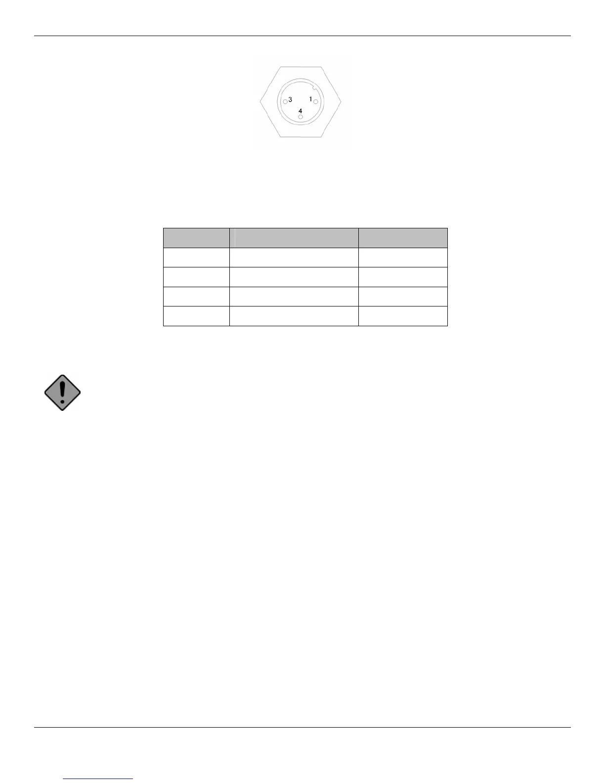
Figure 3 – Power Connector
Table 3 – Power Connector Pin-Out Description
Pin # Function Cable Color
1 Chassis Ground Brown
2 Not connected N/A
3 + Power, 10-60V Blue
4 Ground Black
Mounting the Rhino™ 10
Cautio
n: The touch panel consists of a plastic film covering glass. Use care when handling the Rhino™ 10
during mounting to avoid damage to the touch panel. Physical damage to the panel is NOT COVERED BY
THE WARRANTY.
Add Mounting Base to Computer
Lay the Rhino™ 10 on a flat surface with padding to protect the touch panel (the bag the unit is shipped in works well
for this). If you ordered a keyboard mount, lay one of the flanged plates from the keyboard mount over the studs on the
back of the unit with the flanges bent towards the unit. The ball on the base is offset from the center of the base so
consider which way the offset should be arranged for the mounting distance needed. Use the four 1/4-20 nylon lock
nuts and washers included with the unit and using a wrench or 7/16” (11mm) socket tighten securely (if available, use a
torque setting of 5 ft pounds (6 Nm). Be careful not to over-tighten or you may damage studs.
5

 Loading...