4
3. APPLICATIONS
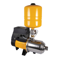
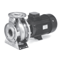
3.1 Above ground water sources (flooded suction)
Installations with flooded suction require a gate valve so water supply can be
turned off for pump removal and servicing, see figure 3.1. There is no need
to install a one-way check valve in the suction pipeline as there is a one-way
check valve installed in the tee piece immediately on top of the DynaDrive
pump discharge.
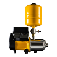
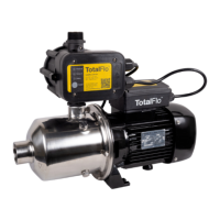
3.2 In-ground water sources (eg suction lift from in ground tank)
Whenever the installation position of the pump is higher than the lowest
water level, a foot valve should be fitted to the end of the suction pipe, see
figure 3.2. Ensure that the foot valve is at least ½ metre (1⅔ feet) below
minimum water level to avoid a vortex of air being drawn into pipe.
In suction lift installations that have an unreliable foot-valve it may
be preferable to remove the check valve in the DynaDrive discharge
tee piece. Doing so will allow the DynaDrive pressure transducer to
“recognise” a loss of water from a suction line, while the DynaDrive
is in standby. Applications of this nature, with long &/or wide suction
lines consist of a considerable volume of water, ie > 100 litres (26
US gallons) in the suction pipe. Temperature variations of the water
may create fluctuations in the pressure of the water, falsely triggering
the DynaDrive to start/stop. In such as case, it is worth considering
upsizing the pressure tank to help absorb these pressure fluctuations. If
concerned, please consult your Davey representative.
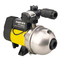
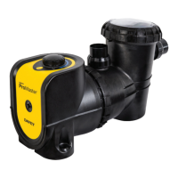
3.3 Spear point installations
When a pump is installed on a spear, or well point, a check valve fitted immediately
on top of the spear point itself, see figure 3.3. Do not install the check valve at the
pump, or at the top of the well. Do not run the pump without water in it.
In suction lift installations that have an unreliable foot-valve it may be preferable to
remove the check valve in the DynaDrive discharge tee piece. Doing so will allow
the DynaDrive pressure transducer to “recognise” a loss of water from a suction line,
while the DynaDrive is in standby. Applications of this nature, with long &/or wide
suction lines consist of a considerable volume of water, ie > 100 litres (26 US gallons)
in the suction pipe. Temperature variations of the water may create fluctuations in
the pressure of the water, falsely triggering the DynaDrive to start/stop. In such as
case, it is worth considering upsizing the pressure tank to help absorb these pressure
fluctuations. If concerned, please consult your Davey representative.
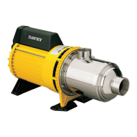
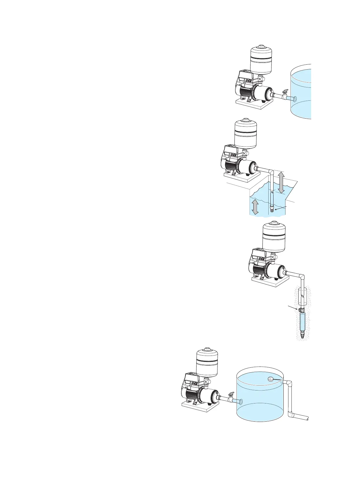
3.4 Connecting mains scheme or town water supply to either
suction, or discharge of pumps and pressure systems
Most Water Supply Authorities have strict regulations
regarding direct connection of pumps to mains water
supplies. In most cases an isolating tank is required
between mains supply and pump, see figure 3.4. Davey
also recommend this method. Directly applied mains
pressure can exceed pump operating pressure and
damage pump. Davey Water Products Pty Ltd cannot
accept responsibility for loss, or damage resulting from
incorrect, or unauthorized installations.
Figure 3.1
MAINS WATER
Figure 3.4
Figure 3.2
> 1m
> 0.5m
Foot valve
(Not Supplied)
Figure 3.3
Check valve