
S
Samantha LoganAug 2, 2025
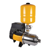
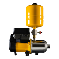
Why won't my Davey DynaDrive DD15-35NPT Water Pump stop running in non-boosting mode?
- SSandy JonesAug 3, 2025
If your Davey water pump doesn't stop running in non-boosting applications, adjust the pump's maximum pressure setting down by 10psi increments until the issue subsides. Also, remember that pressure tank adjustment to 70% of set pressure will be required.