7
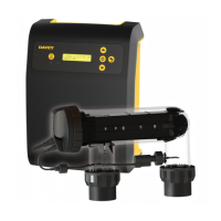
4.2 INSTALLING THE CELL
The ChloroMatic Nipper cell should always by the last appliance in your system. Ensure the cell is installed
after pumps, filters and any heating appliances. To achieve best efficiency, the ChloroMatic Nipper cell should
be installed such that turbulent water is limited as much as possible. When installing a 90° elbow before the
cell’s inlet barrel union, ensure there’s equivalent to 5 x pipe diameter of straight pipe between the elbow and
the union. That is, if the pipe diameter is 40mm, straight pipe entering the barrel union should be no less than
200mm in length. Isolation valves (used where equipment is located below pool water level) should also be
installed no closer than 5 x pipe diameter from the inlet barrel union. This will assist laminar flow.
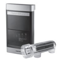
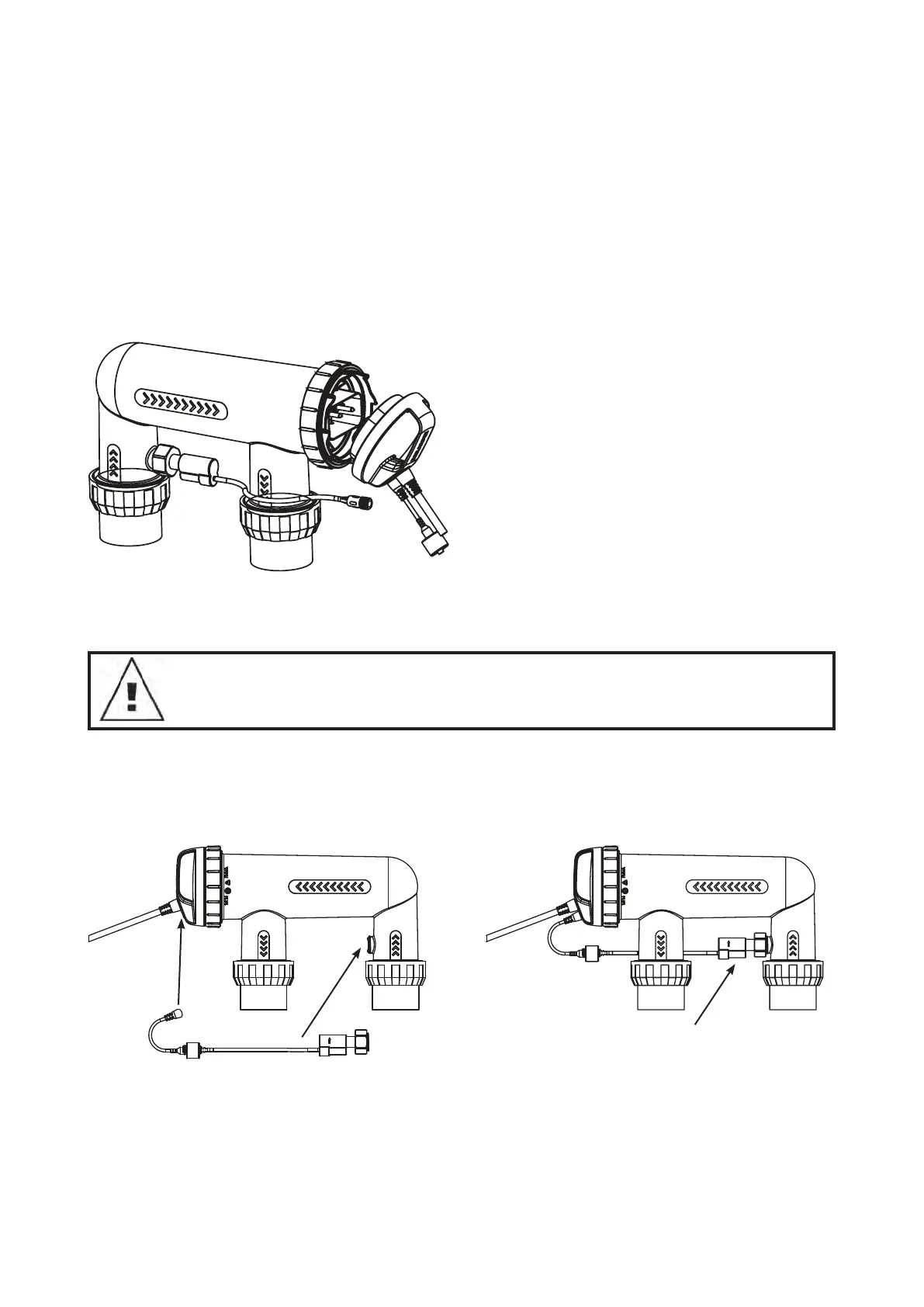
5. CONNECTING THE ELECTROLYTIC CELL TO THE POWER SUPPLY
The Nipper salt water sanitiser uses a reverse polarity electrolytic cell for low maintenance operation. The
ChloroMatic Nipper power supply is fitted with a flexible lead terminated with the cell connectors built into a
plastic moulding. The three in-line connectors are not “polarity sensitive”.
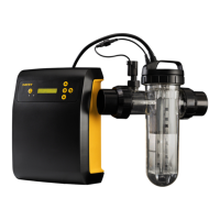
NOTE: The ChloroMatic Nipper cell is supplied with a paddle type flow switch, which is to be installed
on the cell as shown in the diagram on page 4 and connected to the cell lead via the connector on
the end of the cable.
IMPORTANT: The ow switch must be mounted with the highlighted arrow on side of
the switch pointing in the direction of ow.
6. CONNECTING THE FLOW SWITCH TO THE CELL HOUSING
Ensure that the flow switch is installed into the cell housing.
Ensure the flow switch direction is correct (see page 4)
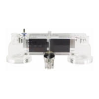
Figure 6.1 Figure 6.2
Fitted
Figure 5.1