Product # 6150, 6150C, 6160, 6160C
I
NTEGRATED
S
ENSOR
S
UITE
I
NSTALLATION
M
ANUAL
For Vantage Pro
TM
or Vantage Pro Plus
TM
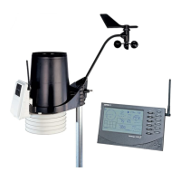
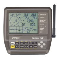
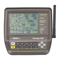
The
Integrated Sensor Suite (ISS)
collects several types of weather readings
for display at your Vantage Pro
TM
console. The data is sent to the console either
through a cable or by wireless transmission, depending on the version.
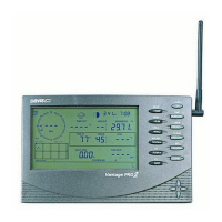
With Wireless Vantage Pro
TM
, the Integrated Sensor Suite (ISS) can be used as
one of eight sensor stations transmitting to your console/receiver(s). See
“Additional Mounting Options” and “Appendix A: Wireless Transmitter IDs”.
The Integrated Sensor Suite for Vantage Pro
TM
measures weather conditions:
✦
Wind Speed
✦
Wind Direction
✦
Rainfall
✦
Outside Temperature
✦
Outside Humidity
The Integrated Sensor Suite for Vantage Pro
Plus
TM
also measures:
✦
Ultraviolet Radiation (UV)
✦
Solar Radiation
Note:
To upgrade a Vantage Pro system to Vantage Pro Plus, see “Appendix B: Optional Accessories”.
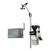
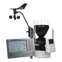
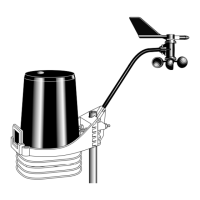
For mounting purposes,
the Integrated Sensor Suite (ISS) consists of two sides:
the anemometer and the rain collector side.
The rain collector side is a white plastic shelf with the black rain collector cone
on top and the white radiation shield below.
The two sides can be mounted either
together
on a single pole (see illustration at
the top of this page), or
separately
. The anemometer has 40' (12 m) of cable.
Note:
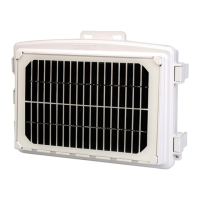
When both sides of the ISS are mounted together with the anemometer arm pointing north, the
solar panel on the rain collector side is facing south. In the Northern Hemisphere, this positions
the solar panel for optimal exposure to the sun. (In the Southern Hemisphere, you will need
to position the solar panel facing north for optimal sun exposure. When mounting both sides
together, this means pointing the anemometer arm south and re-orienting the wind vane.)