(
510
)
732-9229 FAX
(
510
)
670-0589 sales@davisnet.com www.davisnet.com
465 Diablo Ave., Ha
ward, CA 94545-277
3465 Diablo Ave., Hayward, CA 94545-2778 USA
®
t
t
t
WIRELESS VANTAGE PRO2
™
N
S
W
E
N
E
S
E
N
W
S
W
CH
ILL
W
IND
RAIN R
A
TE
i
n
/
h
r
TEM
P
OU
T
HU
M IN
HUM OUT
DA
IL
Y RAIN
in
TEMP
IN
in
m
b
B
AR
O
ME
TER
STATIO
N N
O
.1
F
F
pm
M
P
H
L
ast
2
4h
r
s
hr
E
ve
r
y
1
N
W
S
E
N
6152 6162
6153 6163
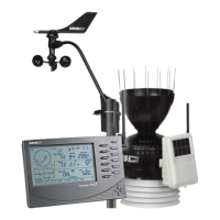
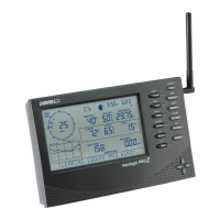
Wireless Vantage Pro2™ &
Vantage Pro2™ Plus Stations
(Including Fan-Aspirated Models)
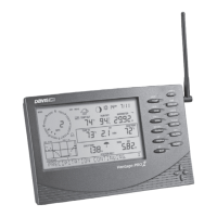
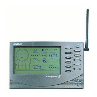
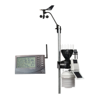
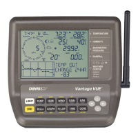
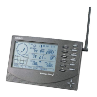
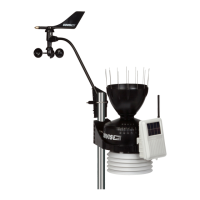
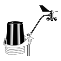
VantagePro2™(6152,61 53)andVantagePro2™Plus(6162, 6163)WirelessWeatherStationsincludetwo
components:theIntegratedSensorSuite(ISS)whichhousesandmanagestheexternal sensorarray,andtheconsole
whichprovidesthe userinterface,datadisplay,andcalculations.TheISSandVantagePro2consolecommunicate
viaan FCC
‐certified,license‐free,spread‐spectrumfrequency‐hopping(FHSS)transmitterandreceiver.User‐
selectabletran smitterIDcodesallowuptoeightstationstocoexistinthesamegeographicarea.Thefrequency
hoppingspreadspectrumtechnologyprovidesgreatercommunicationstrengthoverlongerdistancesandareasof
weakerreception.TheWirelessVantag ePro2
Plusweatherstationincludestwoadditionalsensorsthatareoptional
ontheVantagePro2:theUVsensorandthesolarradiationsensor.
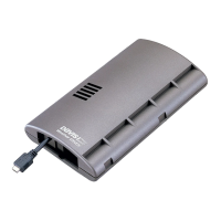
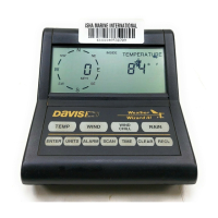
Theconsolemay bepoweredbybatteriesorbytheincludedAC‐poweradapter.ThewirelessISSissolarpowered
withabatterybackup.UseWeatherLink
®
forVan tagePro2andVantageVue
®
toletyourweatherstationinterface
withacom puter,tologweatherdata,andtouploadweatherinformatio ntotheint ernet.
The6152and6162relyonpassiveshieldingtoreducesolar‐radiationinducedtemperatureerrorsintheoutside
temperaturesensorreadings.TheFan‐aspirated6153and6163combinepassiveshielding
withaso lar‐poweredfan
thatdrawsoutsideairinoverthetem peratureandhum iditysensors,providingamuchmoreaccuratetemperature
readingthanthatavailableusingpassiveshieldingalone.
Integrated Sensor Suite (ISS)
Operating Temperature . . . . . . . . . . . . . . . . . . . . . . . . . . -40° to +150°F (-40° to +65°C)
Non-operating Temperature . . . . . . . . . . . . . . . . . . . . . . . -40° to +158°F (-40° to +70°C)
Current Draw (ISS SIM only) . . . . . . . . . . . . . . . . . . . . . . 0.14 mA (average), 30 mA (peak) at 4 to 6 VDC
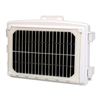
Solar Power Panel . . . . . . . . . . . . . . . . . . . . . . . . . . . . . . 0.5 Watts (ISS SIM), plus 0.75 Watts (Fan-Aspirated)
Battery (ISS SIM /Fan-Aspirated) . . . . . . . . . . . . . . . . . . . CR-123 3-Volt Lithium cell / 2 - 1.2 Volt NiCad C-cells
Battery Life (3-Volt Lithium cell) . . . . . . . . . . . . . . . . . . . . 8 months without sunlight - greater than 2 years depending on solar charging
Battery Life (NiCad C-cells, Fan-Aspirated) . . . . . . . . . . . 1 year
Fan Aspiration Rate (Fan-Aspirated only)
Intake Flow Rate, full sun . . . . . . . . . . . . . . . . . . . . . 190 feet/min. (0.9 m/s)
Intake Flow Rate, battery only. . . . . . . . . . . . . . . . . . 80 feet/min. (0.4 m/s)
Sensor Chamber Flow Rate, full sun . . . . . . . . . . . . . 500 feet/min. (2.5 m/s)
Sensor Chamber Flow Rate, battery only . . . . . . . . . 280 feet/min. (1.4 m/s)
Connectors, Sensor . . . . . . . . . . . . . . . . . . . . . . . . . . . . . Modular RJ-11
Cable Type . . . . . . . . . . . . . . . . . . . . . . . . . . . . . . . . . . . 4-conductor, 26 AWG
Cable Length, Anemometer . . . . . . . . . . . . . . . . . . . . . . . 40’ (12 m) (included) 240’ (73 m) (maximum recommended)
Note: Maximum displayable wind decreases as the length of cable increases. At 140’ (42 m) of cable, the maximum wind speed displayed is 135 mph
(60 m/s); at 240’ (73 m), the maximum wind speed displayed is 100 mph (34 m/s).
Wind Speed Sensor . . . . . . . . . . . . . . . . . . . . . . . . . . . . Solid state magnetic sensor
Wind Direction Sensor . . . . . . . . . . . . . . . . . . . . . . . . . . Wind vane with potentiometer
Rain Collector Type . . . . . . . . . . . . . . . . . . . . . . . . . . . . Tipping bucket, 0.01" per tip (0.2 mm with metric rain adapter), 33.2 in
2
(214 cm
2
)
collection area
Temperature Sensor Type . . . . . . . . . . . . . . . . . . . . . . . . PN Junction Silicon Diode
Relative Humidity Sensor Type . . . . . . . . . . . . . . . . . . . . Film capacitor element
Housing Material . . . . . . . . . . . . . . . . . . . . . . . . . . . . . . . UV-resistant ABS, ASA plastic
DS6152_62_53_63 (Rev. K 9/30/13)