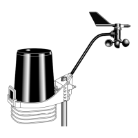
Installing the Anemometer
Weather Wizard III Page 11
ANTENNA MAST OR METAL PIPE
- OUTSIDE DIAMETER 3/4 TO
1 1/4
INCHES (19 TO 32 MM)
1. Make sure that the antenna mast or metal pipe is properly
grounded. If you are not sure, consult a qualified professional.
2. Hold the anemometer base against the pipe and insert the two
U-bolts through the back of the base so that the U-bolts wrap
around the pipe.
3. Place a 1/4-inch washer and a 1/4-20 hex nut over each end of
the U-bolts. Use a wrench to tighten the hex nuts.
METAL MAST OR PIPE - OUTSIDE DIAMETER GREATER THAN 1 1/4 INCHES (32 MM)
1. Obtain two stainless steel hose clamps large enough to fit
around the mast or pipe and the anemometer base. These can
be purchased at your local hardware store.
2. Make sure that the metal mast or pipe is properly grounded. If
you are not sure, consult a qualified professional.
3. Hold the anemometer base against the pipe and fasten the hose
clamps over the anemometer base and around the metal mast
or pipe.
To Attach the Wind Vane
To mount the wind vane, you will need to look at the console display. You may
wish to have a friend or family member on the ground do this for you. Or, you
may wish to bring the console and junction box onto the roof with you.
1. After installing the anemometer, re-insert the plug at the end of the anemometer
cable into the jack marked WIND on the junction box
2. Press WIND on the console until a wind direction reading and the word DIRECTION
appear on the display.
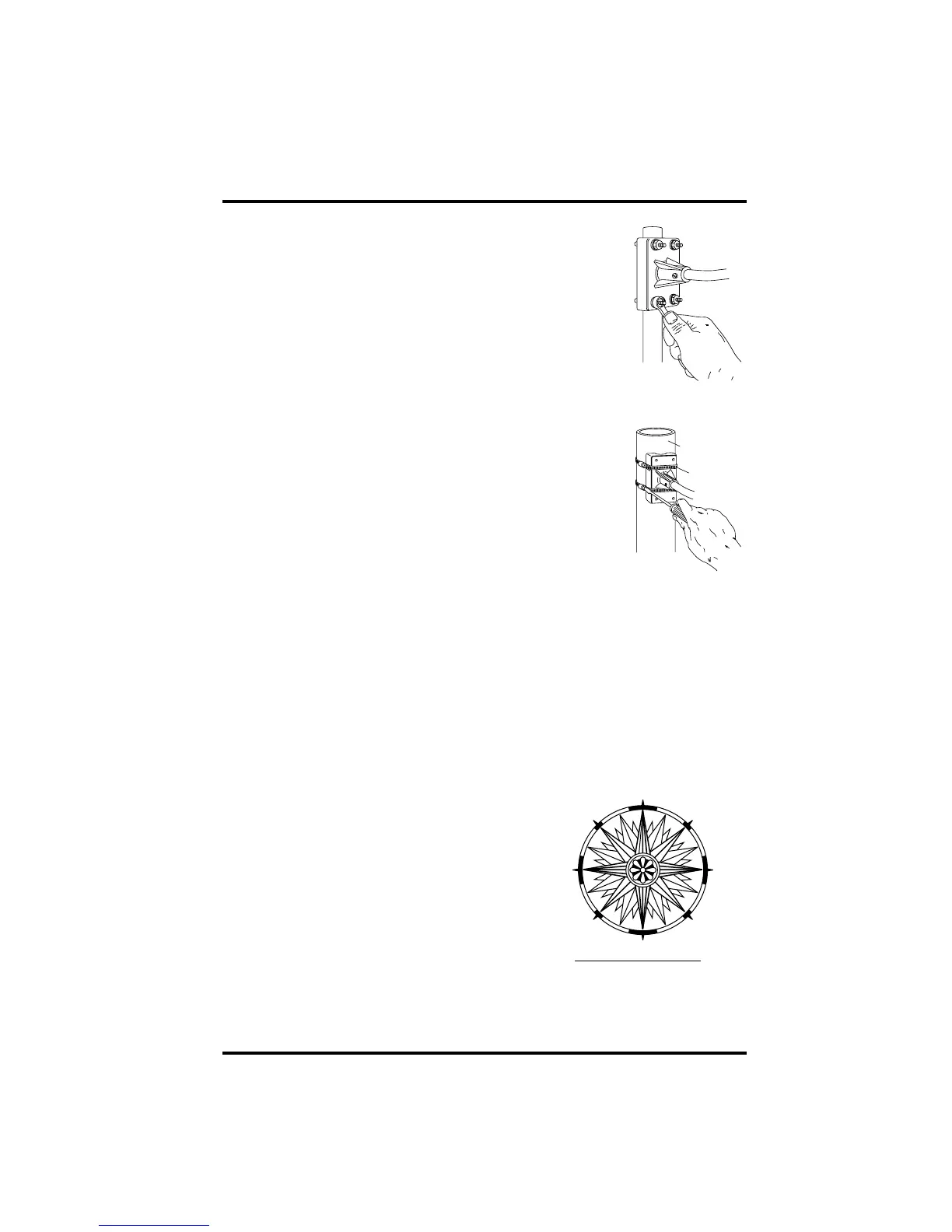
3. Use a compass or local area map to determine which direction (N, S, E, W, NE, etc.)
the anemometer arm is pointing.
4. Use the wind direction chart to find the
degree reading which corresponds to that
direction.
5. Slowly turn the wind direction shaft with your
fingers. Stop turning when the console display
reaches the degree reading obtained in
step 4.
6. Being careful to keep the stainless steel shaft
from turning, place the wind vane on the shaft
with the bullet-shaped nose of the vane point-
ing in the same direction as the arm. Leave
approximately a 1/16-inch (1.5-mm) gap
between the base of the wind vane and the arm.
0° N
180° S
270° W90° E
45° NE315° NW
135° SE225° SW
WIND DIRECTION CHART
 Loading...