3KP64 - 3.15
3000PLUS WITH 5D64 INSTRUCTION MANUAL V. SB.2
SETUP STAGE 4(AX): ABSOLUTE TRANSDUCER CALIBRATION
(
cont’d)
When the
3000PLUS
displays this . . . Do this . . .
ST
and
CL
are lit.
3. FRONT-PANEL CONFIGURATION
AND CALIBRATION
Then press
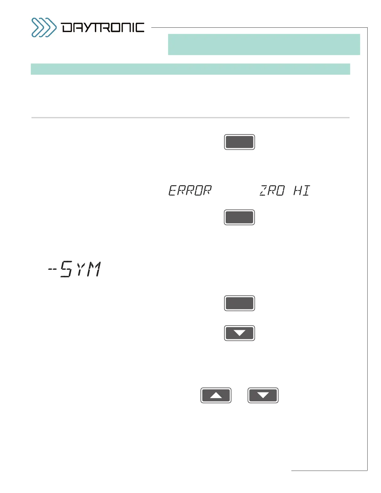
NOTE: The 3000PLUS will now calculate a MODULE INPUT OFFSET
(MIO)
(as explained in Section 4.E and Appendix B). If this calculation
yields an offset that is
too high (absolute value greater than 20%), you
will see a display of
alternating with
Press
to acknowledge the error message. You will be automatically returned
to Step 4(AX).c. Repeat the absolute calibration procedure, but enter
a smaller
OUTPUT ZERO CORRECTION (or a larger FULL-SCALE
OUTPUT
).
4(AX).n. The 3000PLUS lets you modify the slope of the output in the negative
domain in order to make it symmetrical with the positive slope (see
Section 4.E for more details regarding the
NEGATIVE SYMMETRY
(SYM)
parameter). If you want to apply a NEGATIVE SYMMETRY
CORRECTION
, answer “YES” by pressing
If no symmetry correction is required, answer “NO” by pressing
and proceed to
Setup Stage 5 (p. 3.27).
4(AX).o. The display will now show the value you entered in Step 4(AX).k,
above (the desired
FULL-SCALE OUTPUT IN ENGINEERING
UNITS
), but with opposite sign.
Use
and
as explained in Section 3.A to to adjust the displayed number (if nec-
essary) to equal the
desired full-scale output reading in the negative
domain
, expressed in measurement units. The number you enter
here determines the required symmetry correction factor. If no sym-
metry correction is desired, you need not change the initially displayed