3KP64 - 3.18
3000PLUS WITH 5D64 INSTRUCTION MANUAL V. SB.2
SETUP STAGE 4(AV): ABSOLUTE VOLTAGE CALIBRATION
(
cont’d)
When the
3000PLUS
displays this . . . Do this . . .
ST
and
CL
are lit.
3. FRONT-PANEL CONFIGURATION
AND CALIBRATION
If you want the RANGE value to be reset, press
to answer “YES” and proceed to Step 4(AV).c, below.
If you do not want the
RANGE value to be reset, press
to answer “NO.” You will be returned to Step 4(AV).a.
If the 3000PLUS is not able to reset the
RANGE value so that a “legal”
MSF may be calculated from the present calibration numbers, you will
be automatically returned to Step 4(AV).a.
If you got a “RNG HI” (or “RNG LO”) error, you may wish to exit and
restart the setup procedure, this time selecting a lower (or higher}
FULL-SCALE RANGE value in Step 2.b. Or you can continue with the
calibration, but try to increase (or decrease) the effective sensitivity by
increasing (or decreasing) the FULL-SCALE OUTPUT entry.
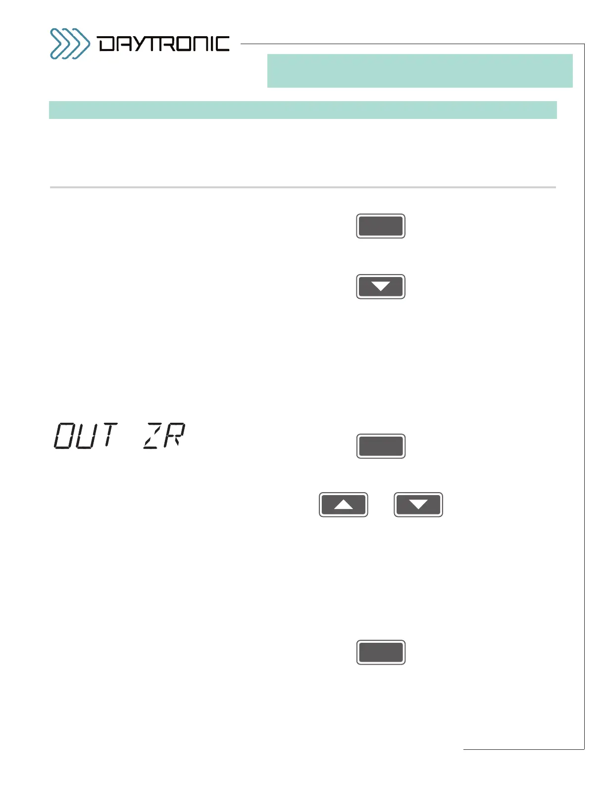
4(AV).c. Press
4(AV).d. The last-entered
OUTPUT ZERO CORRECTION will be displayed
(having the decimal-point precision specified in Step 2.d). Use
and
as explained in Section 3.A to adjust the displayed number to the
desired value. This will normally be the
desired correction (“offset”) to
be continuously applied to the 3000PLUS instrument’s scaled output
channels (1 and 2), expressed in measurement units
(see Section 4.E
for more information on the
MODULE INPUT OFFSET (MIO) parame-
ter). The number should be entered with the desired plus/minus
polarity: a
positive offset value will be algebraically added to the output
signal; a
negative offset value will be algebraically subtracted. The ini-
tial (default) setting is always zero.
Then press
NOTE: The 3000PLUS will now calculate a MODULE INPUT OFFSET
(MIO)
(as explained in Section 4.E and Appendix B). If this calculation
yields an offset that is
too high (absolute value greater than 20%), you
will see a display of