3KP64 - 5.4
3000PLUS WITH 5D64 INSTRUCTION MANUAL V. SB.2
Daytronic Corporation
2211 Arbor Blvd. Dayton, OH 45439 • (800) 668-4745
Tel: (937) 293-2566 • Fax: (937) 293-2586 • www.daytronic.com
defined, Channel 2 will simply track the basic scaled
output, regardless of actual signal behavior.
Like the backout threshold (above), the active peak
defeat threshold can be specified as part of the normal
3000PLUS setup procedure. It can be changed on a
strictly
run-time basis by entering the desired units
value in the “HPT” field in the
“Live Output” window
when Channel 2 is being displayed (see Fig. 11). It may
also be specified at any time by issuing the “write” form
of the
PEAK DEFEAT THRESHOLD (HPT) command
to the 3000PLUS.
Expressed in the active engineering units, the peak
defeat threshold value should not be greater than 20%
of the 3000PLUS instrument’s currently effective
Full
Scale Units (FSU)
value (discussed in Section 1.D).
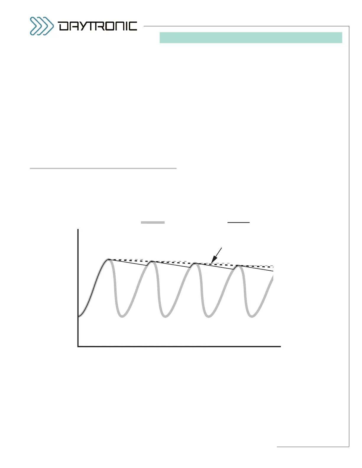
SETTING THE “LEAK RATE”
The 3000PLUS user can specify the rate at which every
signal value held by the “auxiliary” DAC output will
decay, in
percent of full scale per second. This is useful
in the measurement of peak trends in very fast cyclic
processes, and permits capture of rapidly successive
peaks of similar amplitude—as shown in Fig. 19—with-
out having to provide a “reset” for each peak. Typical
applications involve high-speed displacement sensors
in the monitoring of tool or material wear (wear and
metal fatigue of dies, presses, bearings, bushings, etc.)
or of eccentric phenomena like shaft runout or flywheel
wobble.
Like the backout and peak defeat thresholds (above),
the active peak “leak rate” can be specified as part of
the normal 3000PLUS setup procedure. It can be
changed on a strictly
run-time basis by entering the
desired rate value in the “LKR” field in the
“Live Out-
put”
window when Channel 2 is being displayed (see
Fig. 11). It may also be specified at any time by issuing
the “write” form of the
LEAK RATE (LKR) command to
the 3000PLUS.
The desired leak rate should be entered as a positive
number (or zero) representing percent of full scale per
second. You cannot enter a value greater than 3.50 (%).
5. OPERATING CONSIDERATIONS