3KP64 - 5.3
3000PLUS WITH 5D64 INSTRUCTION MANUAL V. SB.2
Daytronic Corporation
2211 Arbor Blvd. Dayton, OH 45439 • (800) 668-4745
Tel: (937) 293-2566 • Fax: (937) 293-2586 • www.daytronic.com
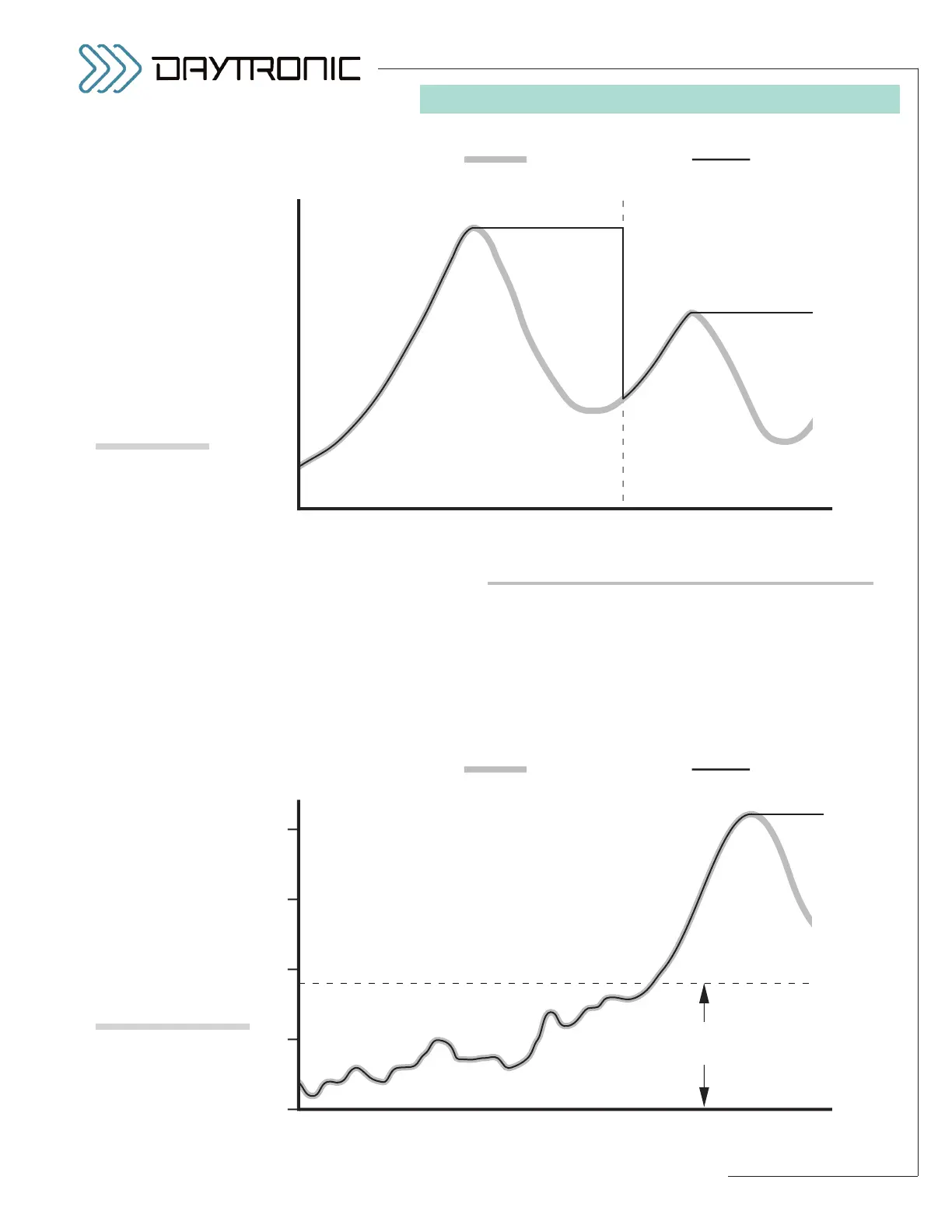
Resetting a peak may also be accomplished by
momentarily bringing the meter’s rear-panel
PEAK
(“PEK”)
terminal to the Logic 0 level, and then immedi-
ately back to
Logic 1 (see Fig. 10.a, Section 2.E). As a
result, Channel 2 will be returned (at least momentarily)
to the existing value of the basic scaled output (Chan-
nel 1).
Fig. 17 shows how a peak reset at time t
1
allows the
capture of successively lower-valued signal maxima.
SETTING THE “PEAK DEFEAT” THRESHOLD
A “PEAK DEFEAT” input threshold expressing in engi-
neering units can be set up in order to prevent induced
low-level signal noise from triggering a “HAVE PEAK”
condition, when analog peak capture is enabled (as
shown in Fig. 18). As long as the value of the “auxiliary”
output remains below the specified threshold, no peak
capture will occur. Within the low-level deadband thus
5. OPERATING CONSIDERATIONS