3KP64 - 5.7
3000PLUS WITH 5D64 INSTRUCTION MANUAL V. SB.2
Daytronic Corporation
2211 Arbor Blvd. Dayton, OH 45439 • (800) 668-4745
Tel: (937) 293-2566 • Fax: (937) 293-2586 • www.daytronic.com
ENABLING/DISABLING LIMITS
When limit monitoring is enabled, the 3000PLUS will
continuously evaluate its “auxiliary” DAC output (Chan-
nel 2) for conformance to the currently specified
high/low setpoint values, activating appropriate relays
and front-panel indication on detection of limit violation
(for LOGIC I/O connections, see Section 2.E).
The active limits status can be specified as part of the
normal 3000PLUS setup procedure—either by means
of the front-panel button menu (as explained in Section
3.B) or the Configurator software (Section 4). It can be
changed on a strictly
run-time basis by selecting “ON”
or “OFF” in the “LIM” field in the Configurator’s
“Live
Output”
window when Channel 2 is being displayed
(see Fig. 11). It may also be specified at any time by
issuing the “write” form of the
LIMITS (LIM) command
to the 3000PLUS, either via the Configurator’s
Send
Command...
window or via a conventional or cus-
tomized “terminal emulation” program (see Section 5.A,
above).
When limits are disabled, the meter’s three front-panel
limit indicator lights will be inactive.
5. OPERATING CONSIDERATIONS
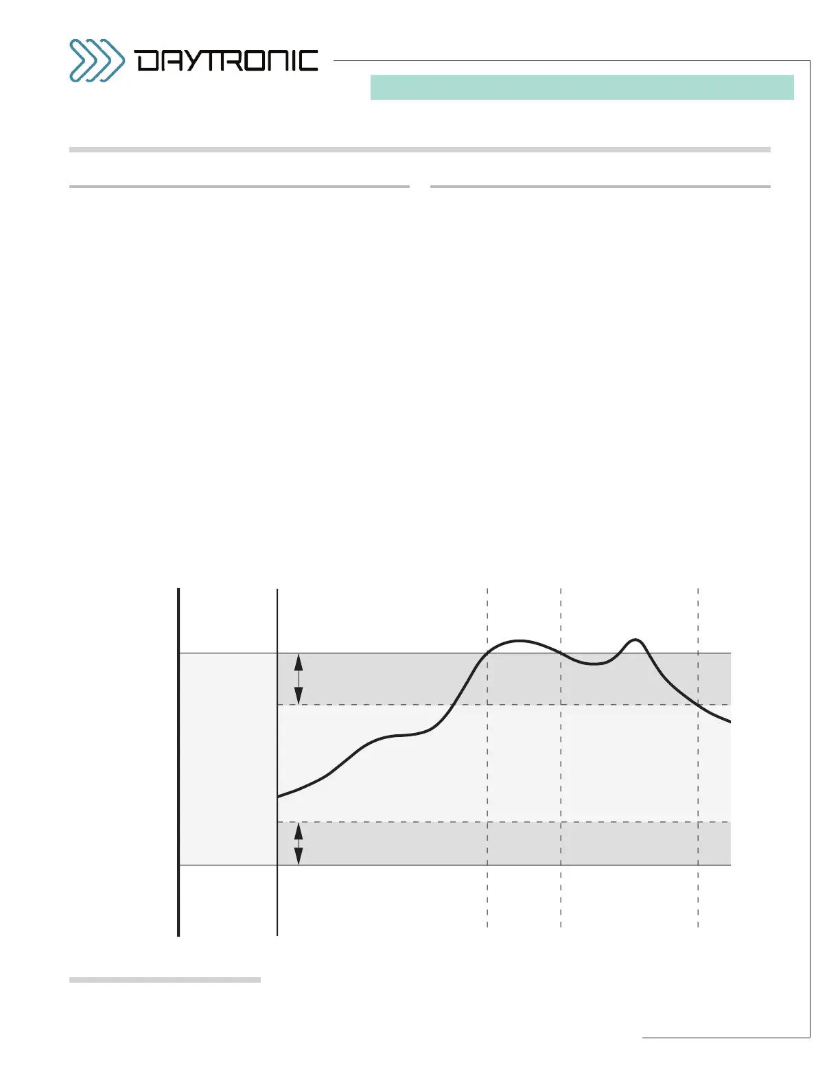
Fig. 21
3000PLUS Limit Zones
SETTING HIGH/LOW LIMITS
By specifying two independent limit setpoints, you can
define the three distinct limit zones shown in Fig. 21:
• “LESS THAN” ZONE (“LO”): the reading for Chan-
nel 2 is less than the current Low Limit
• “BETWEEN” ZONE (“OK”): the reading for Channel
2 is greater than or equal to the current Low Limit
and less than or equal to the current High Limit
• “GREATER THAN” ZONE (“HI”): the reading for
Channel 2 is greater than the current High Limit
The “LESS THAN” or “GREATER THAN” zones may be
effectively extended for
nonlatching limits by means of
a user-specified hysteresis deadband (see below).
Normally entered during 3000PLUS setup, the high/low
limits can be changed on a strictly
run-time basis by
entering desired values in the “HIL” and “LOL” fields,
respectively, in the Configurator’s
“Live Output” win-
dow when Channel 2 is being displayed (see Fig. 11).
They may also be specified at any time by issuing the
“write” forms of the
HIGH LIMIT (HIL) and LOW LIMIT
(LOL)
commands to the 3000PLUS.
(cont’d)
5.E LIMIT MONITORING