OPERATION
Input Impedance &
Terminations
There is
sometimes
a
misunderstanding regarding the
nature
of matching and
bridging inputs, the use
of termi-
nating resistors, and
the relationship
between actual input
impedance and
nominal source
impedance. Most
electronic
outputs
work well when
"terminated" by an
input (con-
nected to an input)
having the same
or
a
higher actual
impedance.
Outputs are usually
overloaded when
terminated by an
impedance that is lower
than the source
impedance. When
the input
impedance
is
nearly the same
impedance as
the source, it is known as a
"matching"
input
When an input is
10-times the source impedance,
or more,
the input is
considered to be a
"bridging" input.
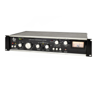
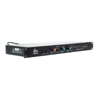
The dbx 160
and 161 have
respective actual input
impedances
of 50,000 ohms
and 25,000 ohms
(they are
high-Z
#
inputs). This
makes the dbx inputs
suitable for use
with virtually
any nominal source
impedance, low or
high.
The dbx inputs
will bridge 150-ohm
or 600-ohm (low-Z)
lines,
and will match 10,000-ohm
or greater impedance
(high-Z) lines. It
seldom
is
necessary to place a
600-ohm
"terminating
resistor" across the input
of the dbx unit. In
fact, most
600-ohm outputs operate
normally when
bridged by a
high impedance; it is as
though no load
were
connected to the source
device. The only
instance where a
terminating resistor
may be required is when
the manu-
facturer of the
source device specifically states
that a
terminating resistor is necessary. In
such cases, there is
usually
a
special
type of output transformer in
the source
device, and the
terminating resistor assures
optimum
frequency
response in that device.
Terminating resistors
are not needed for
the dbx unit to operate
correctly. If
a
150-ohm
or 600-ohm resistor is
specified for the source
device, it
should be installed at
the end of the cable
nearest
the dbx unit in
order
to
minimize possible hum,
noise or
signal
losses in the cable.
•"Z" is an
accepted
abbreviation for
"
impedance
.
"
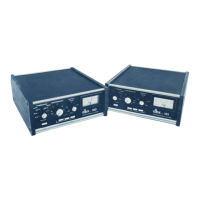
Power
Switch
Depress the
"Power" switch
for the 160 or 161.
The
"BELOW
THRESHOLD"
LED and the
meter lamps should
illuminate.
It is normal for
the
"ABOVE THRESHOLD"
LED
to
flicker with no
input signal
applied during the
time
when the power is
turned on or
off.
Threshold &
Compression Ratio
Adjustments
INITIAL
CONTROL
SETTINGS
THRESHOLD fully
clockwise (3V),
OUTPUT GAIN
at
"12
o'clock" (OdB),
COMPRESSION
RATIO
at
the
appropriate ratio, low
settings for compression
(1:1 to 4:
1
),
high settings
for limiting (10:1 to
infinity).
PROCEDURE
Apply
normal-level program material
to the input. The
BELOW THRESHOLD
LED will remain on, except
when
input levels exceed the threshold setting.
The ABOVE
THRESHOLD LED
indicates
when compression is taking
place. Starting with the THRESHOLD fully clockwise,
rotate it counterclockwise until the
ABOVE THRESHOLD
LED begins
the flicker. At this setting,
compression will
begin
whenever the input level exceeds
the threshold setting.
Further counterclockwise
rotation of the
THRESHOLD
control will
cause compression to begin at a
lower point
relative to
the maximum input level.
For a further
discussion of the use of the
COM-
PRESSION RATIO, and
THRESHOLD controls, refer to
the final
section of this manual,
"COMPRESSION RATIO,
A REVIEW."
NOTE: The 160's
ground-loop compensation
circuitry
and power turn-on turn-off
transient protection circuitry
operate normally at any
settings of front panel controls.
Output Gain
Control Adjustment
When
the 160 or 161 is
used
as
a
compressor,
OUTPUT
GAIN can be used to
increase overall
level that is
partially
decreased by
compression. The
effect is to raise
the average
level
of the program material,
while decreasing its
dynamic
range.
To increase the
gain, rotate the
OUTPUT
GAIN
control clockwise past
the "OdB"
position; to decrease
the
gain, rotate the control
counterclockwise.
Audio signals
often have
peaks that are 20dB
above VU
meter readings
(VU meters
indicate average
levels). Even
when
compressed at a 2:1
ratio, such peaks
can still reach
10dB above VU-indicated
levels. To avoid
clipping, use
an
average input level,
such as
-10
to
+8dB, that is
below the
maximum
specified input levels (+21
dB for
the
160,
+17
dB
for the
161 ).
When the
COMPRESSION
RATIO is set
at a
low factor’,
extreme clockwise
rotation of
OUTPUT
GAIN may cause
the 160 or 161
output stage to clip
program
peaks
. . .
even when
maximum input
levels are
not
exceeded.
Due to
the fact that
20dB of gain can be added
in the
160
or 161's output
stage, raising the output
level
substantially above
the input level may cause
clipping.
It is suggested
that, for normal
operation,
OUTPUT
GAIN
be set at
12 o'clock
(OdB) position.
Meter Calibration &
Use
The meter in the 160 and
161 is factory
calibrated to
read
"0"
at
+4dB (1.23V) output
level. To recalibrate
the
meter,
depress the
INPUT LEVEL meter
function switch.
Feed a 1kHz signal, at
your selected
nominal operating level
(the level
desired for
a
"0"
meter
reading) to the
com-
pressor/limiter input. Then adjust
the 160 or 161
meter
calibration control (on the rear
panel) until the
meter
indicates "OdB".
To check the meter
calibration, rotate
THRESHOLD fully clockwise past the 3
V
position, and
set
COMPRESSION RATIO completely
counterclockwise,
(to
the
"1:1"
position). Connect
an accurate,
VU-reading
voltmeter to the 160
or
161
output terminals,
and adjust
the
OUTPUT GAIN control to produce a
reading on the
outboard meter that is
identical
to
the input level.
Then,
depress
the meter
OUTPUT button on the front panel. If the
160 meter
still reads "OdB",
the unit is properly calibrated.
The 160 or 161 as a
Line Amplifier
To use either model as a
line amplifier, adjust
COM-
PRESSION RATIO
to
its maximum
counterclockwise
position
("1:1"), THRESHOLD
to its
maximum clockwise
position ("3V"), and
OUTPUT GAIN to whatever setting
is needed for the
application. Remember that, as
with any
amplifier, excessive gain may cause output
clipping of high-
level signals (see "Output Gain
Control Adjustment" in
preceding paragraphs). To add
compression, adjust the
COMPRESSION RATIO and the THRESHOLD to
the
desired settings.
*The term
"factor
"
refers to the compression
ratio.
 Loading...