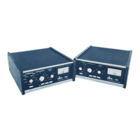
FRONT PANEL
CONTROLS & METERING*
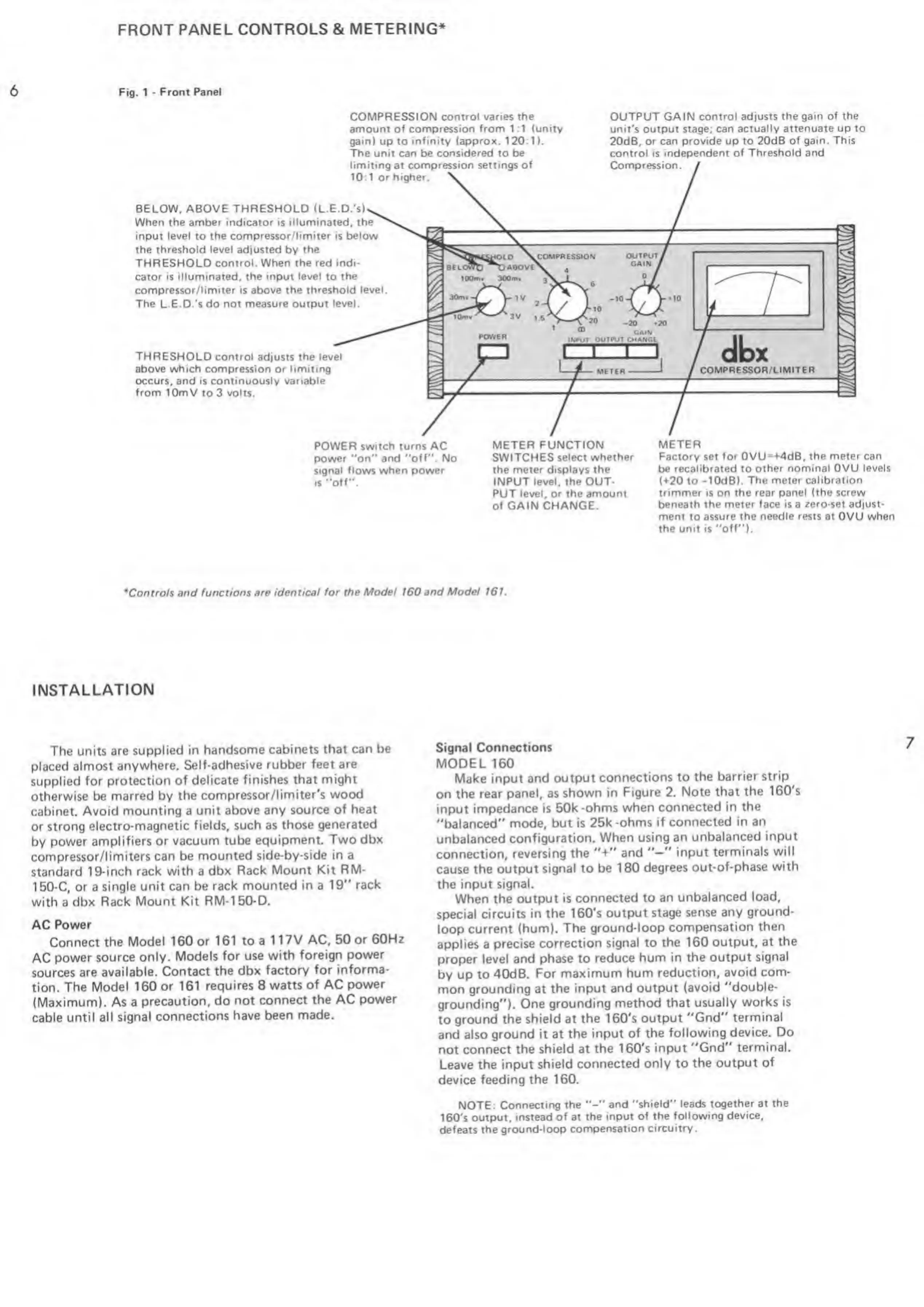
Fig. 1
-
Front
Panel
COMPRESSION control varies the
amount of compression from 1 :1 (unity
gain) up to infinity
(approx.
120:1).
The unit can
be
considered to be
limiting at compression settings
of
10:1 or higher.
OUTPUT GAIN control adjusts the
gain of the
unit's output stage; can
actually attenuate up
to
20dB, or can provide up to 20dB
of gain. This
control is
independent of Threshold and
Compression.
BELOW, ABOVE THRESHOLD (L.E.D.'s)
When the amber indicator is illuminated, the
input level
to
the compressor/limiter is below
the threshold level adjusted by the
THRESHOLD
control. When the red indi-
cator is illuminated,
the input level
to
the
compressor/limiter is above the threshold level
The
L.E.D.'s
do not measure output level.
THRESHOLD
control adjusts the level
above which compression
or
limiting
occurs, and is continuously variable
from lOmV
to 3
volts.
POWER
switch turns AC
power "on" and "off". No
signal flows when
power
is
"off".
METER FUNCTION
SWITCHES select
whether
the meter
displays
the
INPUT level, the OUT-
PUT level, or the
amount
of
GAIN
CHANGE.
METER
Factory set
for
0VU=+4dB,
the meter can
be
recalibrated
to
other nominal OVU levels
(+20 to
-
1 0d
B ) .
The meter calibration
trimmer
is
on the rear panel (the screw
beneath
the meter face is
a
zero-set adjust-
ment to assure the needle rests at OVU when
the unit is
"off").
•
Controls and
functions are identical for the Model 160
and Model 161.
INSTALLATION
The units are
supplied in
handsome cabinets
that can be
placed almost
anywhere.
Self-adhesive
rubber feet are
supplied
for protection
of delicate
finishes that might
otherwise be marred
by the
compressor/limiter's
wood
cabinet. Avoid
mounting a
unit above any source
of heat
or strong
electro-magnetic
fields, such as
those generated
by
power amplifiers
or vacuum tube
equipment.
Two dbx
compressor/limiters
can be mounted
side-by-side in a
standard
19-inch rack
with
a
dbx Rack
Mount Kit RM-
150-C, or a
single unit
can be rack
mounted in a
19"
rack
with a
dbx Rack
Mount Kit
RM-150-D.
AC
Power
Connect
the
Model 160 or
161
to
a
117V AC, 50
or 60Hz
AC
power source only.
Models for use
with foreign
power
sources are
available.
Contact
the dbx factory
for informa-
tion.
The Model
160 or 161
requires 8
watts
of
AC
power
(Maximum). As a
precaution, do
not connect
the AC
power
cable
until all
signal connections
have
been made.
Signal Connections
MODEL 160
Make input
and output
connections to
the barrier
strip
on the rear
panel, as
shown in
Figure
2.
Note that
the 160's
input
impedance is
50k -ohms
when connected
in the
"balanced"
mode, but is
25k -ohms
if connected in
an
unbalanced configuration.
When using
an
unbalanced input
connection, reversing
the
"+"
and
input
terminals
will
cause the output
signal to be 180
degrees
out-of-phase
with
the input
signal.
When the
output is
connected to an
unbalanced load,
special circuits
in the 160's
output
stage sense any
ground-
loop
current
(hum). The
ground-loop
compensation then
applies a
precise
correction signal to
the 160 output, at
the
proper
level and phase to
reduce
hum in the output
signal
by up
to 40dB.
For maximum
hum reduction,
avoid com-
mon
grounding
at
the input
and output
(avoid "double-
grounding"). One
grounding method
that usually
works is
to
ground the shield at
the 160's
output "Gnd"
terminal
and also
ground it at the input
of the
following device. Do
not
connect the shield at
the 160's input
"Gnd"
terminal.
Leave the input shield
connected
only to the
output of
device feeding the 160.
NOTE:
Connecting
the and
"shield" leads together at
the
160's
output,
instead of at
the input of the
following device,
defeats
the ground-loop
compensation
circuitry.
 Loading...