A
REVIEW
Compressor
A variable gain
amplifier whose gain decreases as its input
level increases past
the threshold point.
Limiter
A compressor with a
high compression ratio; the high
ratio maintains essentially
constant output level despite
any
increase in input level
above the threshold.
Compression Ratio
The ratio, in dB, of input
level change above threshold,
to output level change.
A compressor whose output
level
changes IdB for a 2dB
input level change has a
2:1
Compression Ratio.
Threshold
The level
at
which compression
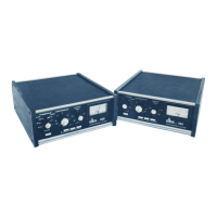
begins, dbx Model 160
and Model 161
compressor/limiters have adjustable thres-
holds. When the input level is
below the set
threshold, and
the Output Gain
control is set at "OdB" (12
o'clock), the
unit
functions
as a 1:1
amplifier (a unity
gain device). When
the input level is above the set
threshold, the unit functions
as a
compressor, or as a
limiter, depending on the
com-
pression ratio selected.
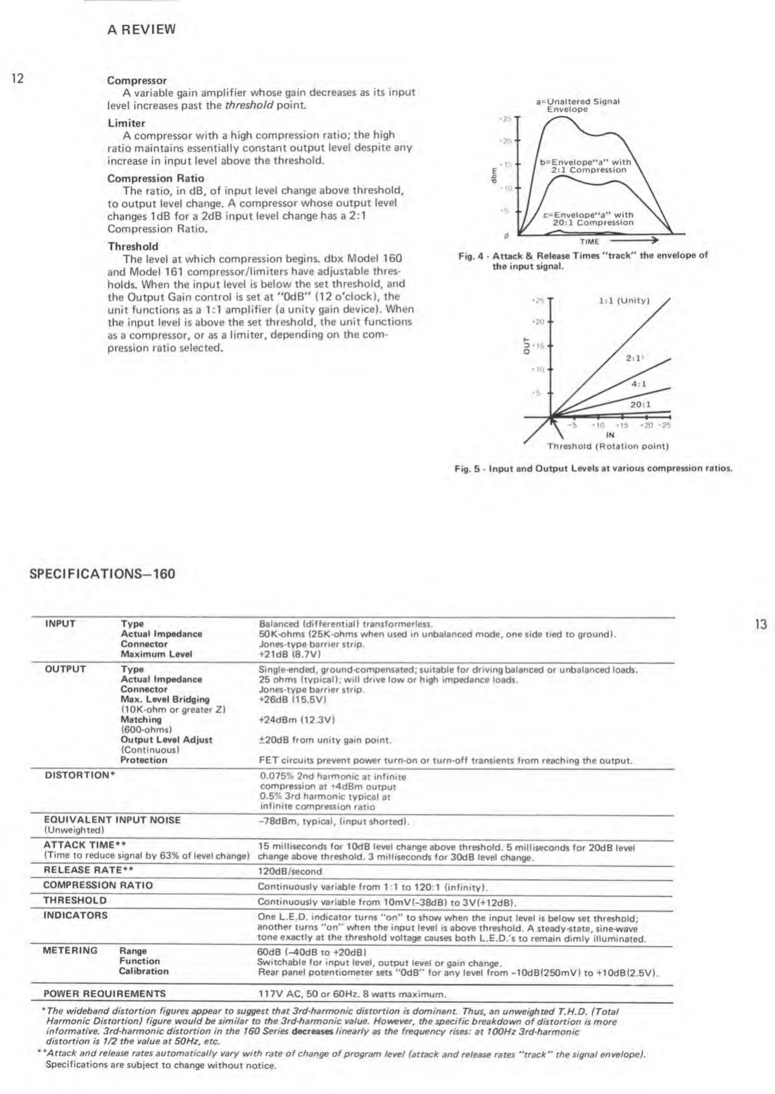
a=Unaltered
Signal
Envelope
Fig.
4
-
Attack & Release
Times "track" the
envelope of
the input signal.
Fig. 5
-
Input and
Output Levels at various
compression ratios.
SPECI FICATIONS— 160
INPUT Type
Actual Impedance
Connector
Maximum Level
Balanced (differential) transformerless.
50K-ohms (25K-ohms when
used
in unbalanced mode, one
side tied to ground).
Jones-type barrier strip.
+21dB (8.7V)
OUTPUT Type
Actual
Impedance
Connector
Max. Level Bridging
(lOK-ohm
or
greater
Z)
Matching
(600-ohms)
Output Level Adjust
(Continuous)
Protection
Single-ended, ground-compensated;
suitable for driving balanced or unbalanced loads.
25 ohms (typical); will drive low or high impedance loads.
Jones-type barrier
strip.
+26dB (15.5V)
+24dBm
(12.3V)
±20dB
from unity gain point.
FET
circuits prevent power turn-on or turn-off transients from reaching the output.
DISTORTION*
0.075% 2nd
harmonic
at infinite
compression
at +4dBm output
0.5%
3rd harmonic typical
at
infinite compression
ratio
EQUIVALENT
INPUT NOISE
(Unweighted)
-78dBm,
typical, (input shorted).
ATTACK TIME**
(Time
to reduce signal
by 63%
of
level change)
15 milliseconds for
10dB
level
change above threshold.
5 milliseconds for
20dB level
change
above threshold.
3
milliseconds
for 30dB level change.
RELEASE RATE**
120dB/second
COMPRESSION RATIO
Continuously variable from
1:1
to
120:1
(infinity).
THRESHOLD
Continuously variable
from 10mV(-38dB)
to 3V(+12dB).
INDICATORS
One L.E.D. indicator turns
"on" to show when the
input level is below
set threshold;
another
turns "on" when the input
level is above threshold.
A steady-state, sine-wave
tone exactly
at
the threshold
voltage
causes both L.E.D.'s
to remain dimly illuminated.
METERING
Range
Function
Calibration
60dB (-40dB
to +20dB)
Switchable for
input level, output level
or gain change.
Rear panel potentiometer sets
"OdB"
for any
level
from
-10dB(250mV) to +10dB(2.5V).
POWER REQUIREMENTS
117V AC, 50 or 60Hz. 8 watts maximum.
'The wideband
distortion figures appear
to suggest that
3rd-harmonic distortion
is dominant. Thus, an unweighted
T.H.D. (Total
Harmonic Distortion) figure would be similar to the 3rd-harmonic value. However, the specific
breakdown of distortion is more
informative. 3rd-harmonic
distortion in the 160 Series decreases linearly as the frequency rises:
at 100Hz 3rd-harmonic
distortion is 1/2 the value at 50Hz, etc.
•
'Attack and release rates automatically vary with rate of change of
program level
(attack and release rates "track" the signal envelope).
Specifications
are subject
to
change
without notice.
 Loading...